
AVPTC 14 Series Installation and Operating Instructions

15
Use the CFM LED (green) to obtain an approximate airflow quantity. The green CFM LED blinks once for each 100 CFM of airflow.
1. Determine the tonnage of the cooling system installed with the air handler. If the cooling capacity is in BTU/hr divide it by 12,000
to convert capacity to TONs.
Example: Cooling Capacity of 30,000 BTU/hr.
30,000/12,000 = 2.5 Tons
2. Determine the proper airflow for the cooling system. Most cooling systems are designed to work with airflows between 350 and
450 CFM per ton. Most manufacturers recommend an airflow of about 400 CFM per ton.
Example: 2.5 tons X 400 CFM per ton = 1000 CFM
The cooling system manufacturer’s instructions must be checked for required air-
flow. Any electronic air cleaners or other devices may require a specific airflow;
consult installation instructions of those devices for requirements.
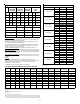
3. Knowing the air handler model, locate the high stage cooling airflow charts i n
the Specification Sheet applicable to your model. Look up the cooling air-
flow determined in step 2 and find the required cooling speed and adjust-
ment setting.
Example: An AVPTC30C14 air handler installed with a 2.5 ton air condi-
tioning system. The airflow needed is 1000 CFM. Looking at the cooling
speed chart for AVPTC30C14, find the airflow closest to 1000 CFM. A
cooling airflow of 1000 CFM can be attained by setting the cooling speed
to “C” and the adjustment to “0” (no adjustment).
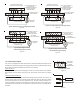
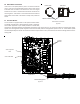
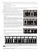
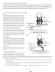
4. Locate the blower speed selection DIP switches on the integrated con-
trol module. Select the desired “cooling” speed tap by positioning
switches 1 and 2 appropriately. If airflow adjustment is required, set dip
switch S8 (trim enable) to ON (trim enable default is off). Then select
the desired “adjust” tap by positioning switches S3 and S4 appropriately.
Refer to the following Airflow Adjust Taps figure for switch positions and
their corresponding taps. Verify CFM by counting the number of times
the green CFM LED blinks, see page 13 for LED locations.
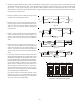
5. Continuous fan speeds that provide 25, 50, 75, and 100% of the air
handler’s maximum airflow capability are selectable via dip switches S12
and S13.
If the air handler’s maximum airflow capability is 2000 CFM and 25%
continuous fan speed is selected, the continuous fan speed will be 0.25 x
2000 CFM = 500 CFM.
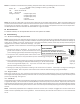
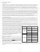
NOTE: Upon start up in communicating mode the circuit board may display an “Ec” error. This is an indication that the dip switches
on the control board need to be configured in accordance with the Electric Heating Airflow Table. Configuring the dip switches
and resetting power to the unit will clear the error code.
Within the thermostat user menu, CTK0* communicating thermostat will display 20 kW for OFF-OFF-ON dip switch selection and
21 kW for OFF-OFF-OFF dip switch selection.
S9
S10
OFF OFF OFF OFFON ON ON ON
21 kW* or
25 kW*
19 kW or
20 kW
Electric Heating Airflow (*indicates factory setting)
15 kW 10 kW
OFF OFF OFF OFFON ON ON ON
8 kW 6 kW 5 kW 3 kW
S11
S9
S10
S11
S9
S10
S11
S9
S10
S11
S9
S10
S11
S9
S10
S11
S9
S10
S11
S9
S10
S11
Figure 25
S1
S2
S1
S2
S1
S2
S1
S2
OFF OFF OFF OFFON ON ON ON
Tap A Tap B
Cooling Airflow Speed Tap (*indicates factory setting)
Tap C Tap D*
Figure 22
S3
S4
OFF OFF OFF OFFON ON ON ON
+5% -5%
Airflow Adjust Taps (*indicates factory setting)
+10% -10%
S3
S4
S3
S4
S3
S4
Dip Switches -
Cooling Airflow and Airflow Adjust Taps
Figure 23
12
13
12
13
12
13
12
13
OFF
OFF
OFF
OFFON
ON
ON ON
25% 50%*
Fan Only Selection (*indicates factory setting)
75% 100%
S12
S13
S12
S13
S12
S13 S13
OFF
OFF
OFF
OFFON
ON
ON ON
Fan Only Selection (*indicates factory setting)
Figure 24