
AVPTC 14 Series Installation and Operating Instructions

14
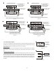
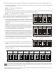
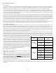
down, water could collect in the motor and may cause premature
failure.
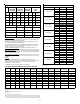
17 Circulator Blower
This air handler is equipped with a multi-speed circulator blower.
This blower provides ease in adjusting blower speeds. The Specifi-
cation Sheet applicable to your model provides an airflow table,
showing the relationship between airflow (CFM) and external static pressure (E.S.P.), for the proper selection of heating and cooling
speeds. The heating blower speed shipped is set at 21kW or 25kW, and the cooling blower speed is set at “D”. These blower speeds
should be adjusted by the installer to match the installation requirements so as to provide the correct electric heating CFM and correct
cooling CFM.
FEMALE CONNECTIONS
SIDE VIEW
W
A
RNING
SOFTW
A
RE VER.
TOP
FRONT VIEW
AVPTC Motor Orientation
Figure 20
COM
TH
TR
DE
CAS
HUM
O
R
2
1
C
2
1
ST4
ST3
ST2
ST1
3A
C
Y2
24VAC
FUSE
W1W2
R
C
G
W1
W2
Y1
3
2
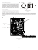
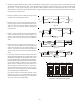
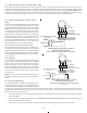
Dip Switches
Green CFM LED
Seven Segment
LED
Auxiliary
Alarms
Communicating Board
Figure 21
16 AVPTC Motor Orientation
If the unit is in the upflow position, there is no need to rotate the
motor. If the unit is in the downflow position, loosen motor mount
and rotate motor as shown in the AVPTC Motor Orientation figure
below. Be sure motor is oriented with the female connections on
the casing down. If the motor is not oriented with the connections