
AVPTC 14 Series Installation and Operating Instructions

13
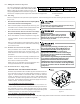
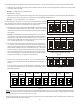
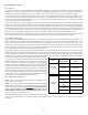
Air Handler Integrated
Control Module
Typical Single-Stage Cool,
Single-Stage Heat Thermostat
Dehumidistat
[Optional]
Remote Condensing Unit
(Single-Stage AC)
NEU
HOT
12RCG
W1 Y1 Y2
O
DEHUM
RCG
W1 Y1
RC
Y
Place Jumper Between Y1
and O for Proper
Dehumidification Operation
and Proper Ramping
Profile Operation
W2
Typical Single-Stage Cooling with Single-Stage Heating
Figure 14
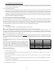
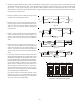
Air Handler Integrated
Control Module
Typical Two-Stage Cool,
Two-Stage Heat Thermostat
Dehumidistat
[Optional]
Remote Condensing Unit
(Two-Stage AC)
NEU
HOT
12RCG
W1 W2 Y1 Y2
O
DEHUM
RCG
W1 W2 Y1 Y2
RC
Y1 Y2
Place Jumper Between Y1
and O for Proper
Dehumidification Operation
and Proper Ramping
Profile Operation
Typical Two-Stage Cooling with Two-Stage Heating
Figure 15
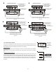
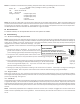
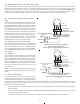
12RC
A
ir Handler
Integrated Control Module
Typical Single-Stage Cool,
Single-Stage Heat
Heat Pump Thermostat
Dehumidistat
[Optional]
G
W1 W2 Y1 Y2
O
DEHUM
Remote Condensing Unit
(Single-Stage HP)
NEU
HOT
W/E
RCG
Y1
O
RC
W1 Y
O
Typical Single-Stage Heat Pump
with Auxiliary/Emergency Heating
Figure 16
12RC
A
ir Handler
Integrated Control Module
Typical Two-Stage Cool,
Two-Stage Heat
Heat Pump Thermostat
Dehumidistat
[Optional]
G
W1 W2 Y1 Y2
O
DEHUM
Remote Condensing Unit
(Two-Stage HP)
NEU
HOT
W/E
RCG
W2 Y1 Y2
O
RC
W1 Y1 Y2
O
Typical Two Stage Heat Pump Heating
and Auxiliary/Emergency Heating
Figure 17
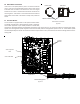
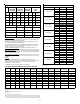
CAS
SWITCH
Figure 19
ON
OFF
Move to the
ON position
to enable
dehumidification
S5 S6 S7 S8
Dip Switches -
Dehumidification Enable
Figure 18
15 Auxiliary Alarm Switch
The control is equipped with two Auxiliary Alarm terminals labeled CAS which can be
utilized with communicating mode setups (typically used for condensate switch wiring
but could be used with compatible C0
2
sensors or fire alarms).
Legacy mode use
In a legacy system (Non-communicating), this feature is not operational. Any auxiliary
alarm switch must be used to interrupt the Y1 signal either to the indoor or outdoor
unit.
Communication mode use
This feature can be activated or deactivated through the thermostat user menus. An
auxiliary alarm switch must be normally closed and open when the base pan’s water
level in the evaporator coil reaches a particular level. The control will respond by turn-
ing off the outdoor compressor and display the proper fault codes. If the switch is de-
tected closed for 30 seconds, normal operation resumes and the error message will be
removed.