
AVPTC 14 Series Installation and Operating Instructions

12
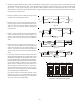
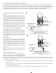
lower blower speed enhances dehumidification of the conditioned air
as it passes through the AC coil. For proper function, a dehumidistat
applied to this air handler must operate on 24 VAC and utilize a switch
which opens on humidity rise.
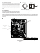
To install/connect a dehumidistat:
1. Turn OFF power to air handler.
2. Secure the dehumidistat neutral wire (typically the white lead) to the screw terminal marked “DEHUM” on the air handler’s
integrated control module.
3. Secure the dehumidistat hot wire (typically the black lead) to the screw terminal marked “R” on the air handler’s integrated
control module.
4. Secure the dehumidistat ground wire (typically the green lead) to the ground screw on the air handler. NOTE: Ground wire may
not be present on all dehumidistats.
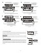
5. To enable the dehumidification function, move the dehumidification dip switch (S7) from OFF to ON. See following figure.
6. Turn ON power to air handler.
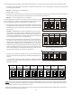
12.4.3 Air Handler With Circuit Breaker Heat Kit
The air handler has a plastic cover on the upper access panel that will require either one or both sections to be removed to allow
the heat kit circuit breaker(s) to be installed. The circuit breakers have lugs for power supply connection. See the HKS Installa-
tion Instructions for further details.
12.5 Low Voltage Connections
Several combinations of low voltage schemes are possible, depending on the presence of a heat kit and whether the heat kit is
single-stage or multi-stage, whether the outdoor section is an air conditioner or heat pump, and whether the system is setup
with a communicating or traditional thermostat. The 24V-control voltage connects the air handler to the room thermostat and
condenser. Low voltage wiring must be copper conductors. A minimum of 18 AWG must be used for installations up to 100 feet.
Low voltage wiring must be connected through the top of the cabinet or either side. See the “Thermostat Wiring” section of this
manual for typical low voltage wiring connections.
13 Achieving 1.4% and 2.0% Airflow Low Leakage Rate
Ensure all the gaskets remain intact on all surfaces as shipped with the unit. These surfaces are areas between the upper tie plate and
coil access panel, blower access and coil access panels, and between the coil access and filter access panels. Ensure upon installation,
that the plastic breaker cover is sitting flush on the blower access panel and all access panels are flush with each other and the cabinet.
With these requirements satisfied, the unit achieves less than 1.4% airflow leakage @ 0.5 inch wc static pressure and less than 2%
airflow leakage @1inch wc static pressure when tested in accordance with ASHRAE Standard 193.
14 24 Volt Wiring
14.1 24 Volt Thermostat Wiring - Non-Communicating Thermostat Connections
NOTE: Wire routing must not interfere with the circulator blower operation or routine maintenance.
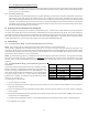
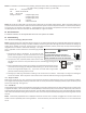
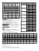
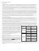
The air handler’s integrated control module provides terminals for “Y1” and “Y2” and “W1” and “W2” thermostat connections. This
allows the air handler to support the systems shown in the following table. Refer to the following figures for typical connections to the
integrated control module. Thermostat wiring entrance holes are located in the top of the blower. Wire routing must not interfere
with circulator blower operation or routine maintenance.
NOTE: A removable plug connector is provided with the control to make thermostat wire connections. This plug may be removed,
wire connections made to the plug, and replaced. It is STRONGLY recommended that you do not connect multiple wires into a single
terminal. Wire nuts are recommended to ensure one wire is used for each terminal. Failure to do so may result in intermittent
operation.
14.2 24 Volt Dehumidistat Wiring - Non-Communicating Thermostat
Connections
The optional usage of a dehumidistat allows the air handler’s circulator
blower to operate at a slightly lower speed during a combined thermo-
stat call for cooling and dehumidistat call for dehumidification. This
COOLING HEAT PUMP HEATING ELECTRIC HEATING
1-STAGE ------ 1- or 2-STAGE
2-STAGE ------ 1- or 2-STAGE
1-STAGE 1-STAGE ------
2-STAGE 2-STAGE ------
1-STAGE 1-STAGE 1- or 2-STAGE
2-STAGE 2-STAGE 1- or 2-STAGE
Table 7