
AVPTC 14 Series Installation and Operating Instructions

11
varying ampacities - be sure to check the temperature rat-
ing used.
Refer to the latest edition of the National Electric Code or
in Canada the Canadian Electric Code when determining
the correct wire size.
12.3 Maximum Overcurrent Protection (MOP)
Every installation must include an NEC (USA) or CEC
(Canada) approved overcurrent protection device. Also,
check with local or state codes for any special regional re-
quirements.
Protection can be in the form of fusing or HACR style circuit
breakers. The Series and Rating Plate provides the maxi-
mum overcurrent device permissible.
NOTE: Fuses or circuit breakers are to be sized larger than
the equipment MCA but not to exceed the MOP.
12.4 Electrical Connections – Supply Voltage
IMPORTANT NOTE: USE COPPER CONDUCTORS ONLY.
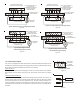
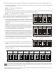
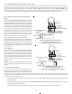
Knockouts are provided on the air handler top panel and sides of the cabi-
net to allow for the entry of the supply voltage conductors, as shown in
Figure 13. If the knockouts on the cabinet sides are used for electrical
conduit, an adapter ring must be used in order to meet UL1995 safety
requirements. An NEC or CEC approved strain relief is to be used at this
entry point. Some codes/municipalities require the supply wire to be en-
closed in conduit. Consult your local codes.
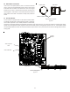
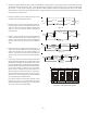
12.4.1 Air Handler Only (Non-Heat Kit Models)
The building supply connects to the stripped black and red wires con-
tained in the air handler electrical compartment cavity. A ground screw is
also contained in this area. Attach the Supply wires to the air handler
conductors as shown in the unit wiring diagram using appropriately sized
solderless connectors or other NEC or CEC approved means.
12.4.2 Air Handler - Non-Circuit Breaker Heat Kits
A terminal block is provided with the HKS kit to attach the power supply and air handler connections. Follow the HKS Installation
Manual and wiring diagram for complete wiring details.
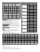
12.1 Building Electrical Service Inspection
This unit is designed for single-phase electrical supply
only. DO NOT OPERATE ON A THREE-PHASE POWER
SUPPLY. Measure the power supply to the unit. The
supply voltage must be measured and be in agreement
with the unit nameplate power requirements and within the range shown.
12.2 Wire Sizing
Wire size is important to the operation of your equipment. Use the following check list when selecting the appropriate wire size
for your unit.
• Wire used must carry the Minimum Circuit Ampacity (MCA)
listed on the unit’s Series and Rating Plate.
• Refer to the NEC (USA) or CSA (Canada) for wire sizing. The
unit MCA for the air handler and the optional electric heat
kit can be found on the unit Series and Rating Plate.
• Wire must be sized to allow no more than a 2% voltage
drop from the building breaker/fuse panel to the unit.
• Wires with different insulation temperature rating have
HIGH VOLTAGE!
To avoid property damage, personal injury or death
due to electrical shock, this unit MUST have an
electrical ground. The
electrical ground circuit may consist of an
appropriately sized electrical wire connecting the
ground lug in the unit control box to the building
electrical service panel.
Other methods of grounding are permitted if performed
in accordance with the National Electric Code
(NEC)/American National Standards Institute
(ANSI)/National Fire Protection Association (NFPA) 70
and local/state codes. In Canada, electrical grounding
is to be in accordance with the Canadian Electric Code
(CSA) C22.1.
uninterrupted, unbroken
FIRE HAZARD!
To avoid the risk of property damage, personal injury
or fire, use only copper conductors.
HIGH VOLTAGE!
Failure to do so may cause property damage,
personal injury or death.
Disconnect ALL power before servicing.
Multiple power sources may be present.
ELECTRICAL VOLTAGE
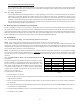
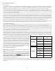
Table 6
Nominal Input Minimum Voltage Maximum Voltage
208-240 197 253
Side of
Cabinet
Top of
Cabinet
KNOCK-OUT FOR ELECTRICAL CONNECTIONS
Figure 13