
AVPTC 14 Series Installation and Operating Instructions

10
dimension must be less than 23-½”x20”) filter can be installed on a B, C and D cabinet respectively (the cabinet size is the seventh letter
of the model number).
11 Electric Heat
Refer to the installation manual provided with the electric heat kit
for the correct installation procedure. All electric heat must be
field installed. If installing this option, the ONLY heat kits that are
permitted to be used are the HKS series. Refer to the air handler
unit’s Serial and Rating plate or the HKS specification sheets to
determine the heat kits compatible with a given air handler. No
other accessory heat kit besides the HKS series may be installed in these air handlers.
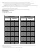
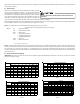
The heating mode temperature rise is dependent upon the system airflow, the supply voltage, and the heat kit size (kW) selected. Use
data provided in Tables 3, 4 and 5 to determine the temperature rise (°F).
NOTE: For installations not indicated above the following formula is to be used:
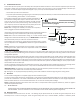
TR = (kW x 3412) x (Voltage Correction) / (1.08 x CFM)
Where: TR = Temperature Rise
kW = Heater Kit Actual kW
3412 = Btu per kW
VC* = .96 (230 Supply Volts)
= .92 (220 Supply Volts)
= .87 (208 Supply Volts)
1.08 = Constant
CFM = Measured Airflow
VC* (Voltage Correction)
NOTE: The Temperature Rise Tables can also be used to estimate the air handler airflow delivery. When using these tables for this
purpose set the room thermostat to maximum heat and allow the system to reach steady state conditions. Insert two thermometers,
one in the return air and one in the supply air. The temperature rise is the supply air temperature minus the return air temperature.
Using the temperature rise calculated, CFM can be estimated from the TR formula above. See Spec Sheets and/or Service Manual for
more information.
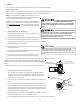
12 Electrical and Control Wiring
IMPORTANT: All routing of electrical wiring must be made through provided electrical knockouts. Do not cut, puncture or alter the
cabinet for electrical wiring.
220/1/60 SUPPLY VOLTAGE - TEMP. RISE °F
Table 3
230/1/60 SUPPLY VOLTAGE - TEMP. RISE °F
Table 2
208/1/60 SUPPLY VOLTAGE - TEMP. RISE °F
Table 4
MINIMUM CFM REQUIREMENTS FOR HEATER KITS
Table 5
Do not operate this product without all the ductwork
attached.
3568101519/2025
800
12 19 23 31 37 56
1000
9 1519253044
1200
8 12152125374962
1400
7 11131821324253
1600
6 9 12 15 19 28 37 46
1800
5 8 10 14 16 25 33 41
2000
5 7 9 1215223037
CFM
HEAT KIT NOMINAL kW
3568101519/2025
800
11 18 22 30 35 54
1000
9 1418242842
1200
7 12152024354759
1400
6 10131720304051
1600
6 9 11 15 18 27 35 44
1800
5 8 10 13 16 24 31 39
2000
4 7 9 1214212835
CFM
HEAT KIT NOMINAL kW
3568101519/2025
800
10 17 21 28 33 52
1000
8 1317222740
1200
7 11141922334556
1400
6 10121619293848
1600
5 8 10 14 17 25 33 42
1800
5 7 9 1215223037
2000
4 7 8 1113202733
CFM
HEAT KIT NOMINAL kW
3
5 6 8 10 15 19 20 25
AVPTC25B14 550 650 700 800 850 875
AVPTC29B14 550 650 700 800 875 875
AVPTC37B14 550 650 700 800 875 1050
AVPTC31C14 850 900 1000 1170 1345
AVPTC37C14 850 900 1000 1170 1345 1345
AVPTC59C14 1170 1170 1170 1170 1345 1345
AVPTC37D14 1240 1240 1240 1240 1520 1520
AVPTC59D14 1240 1240 1240 1240 1520 1520
AVPTC49D14 1250 1300 1500 1550 1720
AVPTC61D14 1250 1300 1500 1550 1780 1850 1850
Model
Heater (KW)