
AVPTC Service Manual

SERVICING
34
between the thermostat and subsystems (indoor/outdoor
unit) and between subsystems is the key to unlocking the
benefits and features of the ComfortNet system.
Two-way digital communications is accomplished using
only two wires. The thermostat and subsystem controls are
powered with 24 VAC Thus, a maximum of 4 wires between
the equipment and thermostat is all that is required to operate
the system.
AIRFLOW CONSIDERATIONS
Airflow demands are managed differently in a fully communi-
cating system than they are in a legacy wired system. The
system operating mode (as determined by the thermostat)
determines which unit calculates the system airflow demand.
If the indoor unit is responsible for determining the airflow
demand, it calculates the demand and sends it to the ECM
motor. If the outdoor unit or thermostat is responsible for
determining the demand, it calculates the demand and
transmits the demand along with a fan request to the indoor
unit. The indoor unit then sends the demand to the ECM
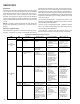
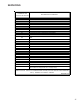
motor. The following table lists the various ComfortNet™
systems, the operating mode, and airflow demand source.
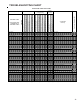
For example, assume the system is an air conditioner
matched with an air handler. With a call for low stage cooling,
the air conditioner will calculate the system’s low stage
cooling airflow demand. The air conditioner will then send a
fan request along with the low stage cooling airflow demand
to the air handler. Once received, the air handler will send the
low stage cooling airflow demand to the ECM motor. The
ECM motor then delivers the low stage cooling airflow. The
table below lists the nominal high and low stage airflow for the
ComfortNet air conditioners and heat pumps.
High Low High Low
*SZC160241 800 600 800 600
*SZC160361 1200 800 1200 800
*SZC160481 1550 1100 1550 1100
*SZC160601 1800 1210 1800 1210
*SZC180361 1250 850 1250 850
*SZC180481 1750 1210 1750 1210
*SZC180601 1750 1210 1750 1210
Cooling Heating
Models
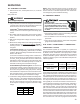
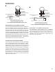
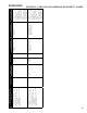
CTK0* WIRING
A removable plug connector is provided with the control to
make thermostat wire connections. This plug may be re-
moved, wire connections made to the plug, and replaced. It
is strongly recommended that multiple wires into a single
terminal be twisted together prior to inserting into the plug
connector. Failure to do so may result in intermittent opera-
tion. Typical 18 AWG thermostat wire may be used to wire the
system components. However, communications reliability
may be improved by using a high quality, shielded, twisted
pair cable for the data transmission lines. In either case, 100
feet is the maximum length of wire between indoor unit and
outdoor unit, or between indoor unit and thermostat.
1
2
R
C
12RC
12RC
CTK0*
Thermostat
CT™ Compatible
Modular Blower
Integrated Control Module
CT™ Compatible AC/HP
Integrated Control Module
System Wiring Using Four-Wires
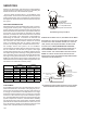
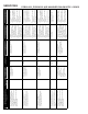
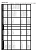
CTK 01/ 02 TWO-WIRE OUTDOOR, FOUR-WIRE INDOOR WIRING
TWO WIRES ONLY MAY BE UTILIZED BETWEEN THE INDOOR AND
OUTDOOR
UNITS. FOR THIS WIRING SCHEME, ONLY THE DATA
LINES
, 1 AND 2, ARE REQUIRED BETWEEN THE INDOOR AND
OUTDOOR
UNITS. A 40VA, 208/230 VAC TO 24 VAC
TRANSFORMER MUST BE INSTALLED IN THE OUTDOOR UNIT TO
PROVIDE
24 VAC POWER TO THE OUTDOOR UNIT’S ELEC-
TRONIC CONTROL. THE TRANSFORMER IS INCLUDED WITH THE
CTK0* KIT. SEE KIT INSTRUCTIONS FOR MOUNTING AND
WIRING
INSTRUCTIONS. FOUR WIRES ARE REQUIRED BETWEEN
THE
INDOOR UNIT AND THERMOSTAT.
1
2R
C
12RC
12
RC
CTK0*
Thermostat
CT Compatible
Modular Blower
Integrated Control Module
CT Compatible
AC/HP Integrated
Control Module
40VA Transformer (included in
CTK0*** kit)
208/230 VAC
24 VAC
System Wiring using Two-Wires between Furnace and AC/
HP and Four-Wires between Furnace and Thermostat