
AVPTC Installation Instructions ComfortBridge
3
2 ShippingInspecon
Always transport the unit upright; laying the unit on its side or top
during transit may cause equipment damage. The installer should in-
spect the product upon receipt for shipping damage and subsequent
invesgaon is the responsibility of the carrier. The installer must
verify the model number, specicaons, electrical characteriscs,
and accessories are correct prior to installaon. The distributor or
manufacturer will not accept claims from dealers for transportaon
damage or installaon of incorrectly shipped units.
2.1 Parts
Also inspect the unit to verify all required components are
present and intact. Report any missing components imme-
diately to Goodman or to the distributor. Use only factory
authorized replacement parts (see Secon 5). Make sure to
include the full product model number and serial number
when reporng and/or obtaining service parts.
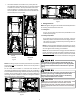
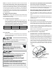
2.2 Handling
Use cauon when transporng/carrying the unit. Do not move
unit using shipping straps. Do not carry unit with hooks or sharp
objects. The preferred method of carrying the unit aer arrival
at the job site is to carry via a two-wheel hand truck from the
back or sides or via hand by carrying at the cabinet corners.
3 Codes&Regulaons
This product is designed and manufactured to comply with appli-
cable naonal codes. Installaon in accordance with such codes
and/or prevailing local codes/regulaons is the responsibility of the
installer. The manufacturer assumes no responsibility for equipment
installed in violaon of any codes or regulaons.
TheUnited States Environmental ProteconAgency(EPA) has
issuedvariousregulaonsregardingtheintroduconanddisposal
ofrefrigerants.Failuretofollowtheseregulaonsmayharmthe
environmentandcanleadtotheimposionofsubstanalnes.
Should you have any quesons please contact the local oce of the
EPA and/or refer to EPA’s website www.epa.gov.
4 Replacement Parts
When reporng shortages or damages, or ordering repair parts,
give the complete product model and serial numbers as stamped
on the product. Replacement parts for this product are available
through your contractor or local distributor. For the locaon of your
nearest distributor consult the white business pages, the yellow
page secon of the local telephone book or contact:
HOMEOWNER SUPPORT
GOODMAN MANUFACTURING COMPANY, L.P.
19001 KERMIER ROAD,
WALLER, TX 77484
(877) 254-4729
5 Pre-InstallaonConsideraons
5.1 Preparaon
Keep this document with the unit. Carefully read all instruc-
ons for the installaon prior to installing product. Make sure
each step or procedure is understood and any special consid-
eraons are taken into account before starng installaon.
Assemble all tools, hardware and supplies needed to complete
the installaon. Some items may need to be purchased locally.
Make sure everything needed to install the product is on hand
before starng.
5.2 System Matches
The entire system (combination of indoor and outdoor
secons) must be manufacturer approved and Air-Condi-
oning, Heang, and Refrigeraon Instute (AHRI) listed.
NOTE: Installaon of unmatched systems is not permied.
Damage or repairs due to installaon of unmatched systems
is not covered under the warranty.
5.3 InterconnecngTubing
Give special consideraon to minimize the length of refrigerant
tubing when installing air handlers. Refer to Remote Cooling/
Heat Pump Service Manual RS6200006, and TP-107 Long Line
Set Applicaon R-410A for tubing guidelines. If possible, allow
adequate length of tubing such that the coil may be removed
(for inspecon or cleaning services) from the cabinet without
disconnecng the tubing.
5.4 Clearances
The unit clearance from a combusble surface may be 0”.
However, service clearance must take precedence. A minimum
of 24” in front of the unit for service clearance is required.
Addional clearance on one side or top will be required for
electrical wiring connecons. Consult all appropriate reg-
ulatory codes prior to determining nal clearances. When
installing this unit in an area that may become wet (such as
crawl spaces), elevate the unit with a sturdy, non-porous ma-
terial. In installaons that may lead to physical damage (i.e. a
garage) it is advised to install a protecve barrier to prevent
such damage. Always install units such that a posive slope
in condensate line (1/4” per foot) is allowed.
5.5 HorizontalApplicaons
If installed above a nished living space, a secondary drain
pan (as required by many building codes), must be installed
under the enre unit and its condensate drain line must be
routed to a locaon such that the user will see the condensate
discharge.
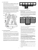
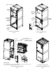
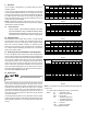
6 InstallaonLocaon
NOTE: These air handlers are designed for indoorinstallaononly.
The AVPTC**14** product line may be installed in one of the up-
ow, downow, horizontal le or horizontal right orientaons as
shown in Figures 2, 3, 4 and 5. The unit may be installed in upow
or horizontal le orientaon as shipped (refer to specic secons
for more informaon).
Minor eld modicaons are necessary to convert to downow
or horizontal right as indicated in below secons.