
Install Instructions

9
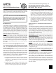
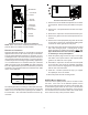
WRAPPER
INSULATION
JACKET
ZEE COIL
SUPPORT
WRAPPER
STIFFENER
DRAIN PAN
INSULATION KIT
BLOWER
ASSEMBLY
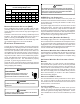
Downflow Conversion - Conversion Completion
NOTE: When converted to downflow position the coil may
protrude above the cabinet on some models.
HORIZONTAL CONVERSION
Dedicated Downflow models are not suitable for horizontal
application and must not be used for this type of installation.
The only field modification required for conversion to “Hori-
zontal Right-Hand” is the removal of the plastic knockouts in
the horizontal panel drain connections. To prevent the hori-
zontal drain pan from sweating in high humidity applications,
it is recommended that a horizontal drain pan insulation
(DPIH) accessory kit be used. NOTE: The DPIH insulation
kit is not supplied with this product and should be purchased
separately. See Horizontal Drain Pan Insulation Kits table
for the correct DPIH kit.
AVPTC Model Insulation Kit
1830 DPIH36-42
3137
4260
DPIH48-61
Horizontal Drain Pan Insulation Kits
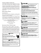
The following describes converting to “Horizontal Left-Hand”.
Conversion to downflow MUST be performed in an area that
allows access to all sides prior to placing the air handler in
its final location. See Horizontal Left-Hand Conversion fig-
ure below.
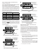
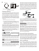
Horizontal Left-Hand Conversion
1. Remove two screws beside the liquid line on the lower
access panels. Remove the (3) air handler access pan-
els.
2. Remove the “J” shaped bracket that retains the evapo-
rator coil.
3. Slide out the evaporator coil and horizontal drain pan.
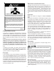
4. Remove the gasket from the horizontal pan drain con-
nections.
5. Remove the oval shaped plastic plug from the left side
access panel. Remove the oval shaped rubber gasket
seal from the lower right side access panel.
6. The drain connections for the horizontal pan are sealed
with a thin coating of plastic. Carefully knock out this
plastic seal with a screwdriver and hammer.
Note: The
upper drain will become the secondary drain which
is mandatory in many municipalities .
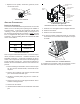
7. Install the plastic plug removed in step 5 to the right
side lower access panel and the oval shaped rubber
gasket to the lower left access panel.
8. Reinstall the evaporator coil with the horizontal panel
on the left side. Note: Push the assembly completely
to the rear to ensure the engagement of the upflow pan
with the rear channel bracket.
9. Install the “J” bracket (removed in step 2) to support
the upflow pan to the tie channel.
10. Attach all panels and the metering device.
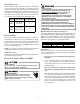
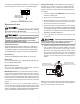
AVPTC MOTOR ORIENTATION
If the unit is in the upflow position, there is no need to rotate
the motor. If the unit is in the downflow position, loosen
motor mount and rotate motor as shown in the AVPTC Mo-
tor Orientation figure below. Be sure motor is oriented with
the female connections on the casing down. If the motor is
not oriented with the connections down, water could collect
in the motor and may cause premature failure.