
Install Instructions

7
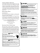
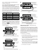
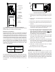
To enable the dehumidification function, move the dehumidi-
fication dipswitch from OFF to ON. See following figure.
S7
S8
ONOFF
DEHUM
Unused
Move to the ON
position to enable
dehumidification
Dipswitches - Dehumidification Enable
R
EFRIGERANT
L
INES
This product is factory-shipped under pressure. Follow
these instructions to prevent injury.
A quenching cloth is strongly recommended to prevent
scorching or marring of the equipment finish when
welding close to the painted surfaces. Use brazing
alloy of 5% minimum silver content.
TUBING PREPARATION
All cut ends are to be round, burr free, and clean.
Failure to follow this practice increases the chances
for refrigerant leaks. The suction line is spun closed
and requires pipe cutters to remove the closed end.
POST BRAZING
Quench all welded joints with water or a wet rag.
PIPING SIZE
For the correct tubing size, follow the specification for
the condenser/heat pump.
SPECIAL INSTRUCTIONS
This coil comes equipped with a thermostatic expansion
valve (TXV) for refrigerant management.
IMPORTANT NOTE: Torch heat required to braze tubes of
various sizes is proportional to the size of the tube. Tubes of
smaller size require less heat to bring the tube to brazing
temperature before adding brazing alloy. Applying too much
heat to any tube can melt the tube. Service personnel must
use the appropriate heat level for the size of the tube being
brazed.
NOTE: The use of a heat shield when brazing is
recommended to avoid burning the serial plate or the finish
on the unit. HEAT TRAP OR WET RAGS SHOULD BE
USED TO PROTECT HEAT SENSITIVE COMPONENTS
SUCH AS SERVICE VALVES AND TXV VALVES.
IMPORTANT NOTE: Sensing bulbs are not permanently
installed at the factory to prevent accidental damage
during brazing. Be sure to follow this checklist step-by-
step to ensure the sensing bulb is not damaged during
installation.
1. Loosen the 13/16 nut 1 TURN ONLY. No pressure loss
indicates possible leak.
2. Remove the nut and discard the cap.
3. Follow the instructions on the caution label, and remove
the two mounting screws on the lower access panel.
Then remove the lower access panel.
4. Remove the large front panel and remove the sensing
bulb from suction manifold. TO PREVENT DAMAGE
TO SENSING BULB, ENSURE BULB IS NOT NEAR
FLAME OR IN CONTACT WITH SUCTION LINE OR
MANIFOLD DURING BRAZING.
5. Use a tube cutter to remove the spin closure on the
suction line.
Excessive torque can cause orifices to stick. Use the
proper torque settings when tightening orifices.
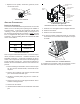
6. Replace sensing bulb to horizontal portion of suction
line just inside cabinet. Place bulb parallel with suction
line between 10 o’clock and 2 o’clock position. Secure
bulb to line with strapping provided in literature enve-
lope. Insulate sensing bulb to line with self-adhesive
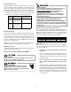
insulation provided in the envelope. See the following
figures for correct bulb placement and strapping infor-
mation.
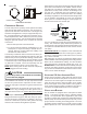
REFRIGERANT BULB
MUST BE POSITIONED
BETWEEN 10 & 2 O’CLOCK
REFRIGERANT BULB
MUST BE POSITIONED
BETWEEN 10 & 2 O’CLOCK
NOTE: The sensing bulb must be permanently located. A
heat shield, heat trap, or wet rag must be used during braz-
ing to prevent damage to the TXV valve.