
Install Instructions

6
24 VOLT THERMOSTAT WIRING - NON-COMMUNICATING
THERMOSTAT CONNECTIONS
NOTE: Wire routing must not interfere with the circulator
blower operation or routine maintenance.
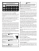
The air handler’s integrated control module provides termi-
nals for “Y1” and “Y2” and “W1” and “W2” thermostat con-
nections. This allows the air handler to support the systems
shown in the table below. Refer to the following figures for
typical connections to the integrated control module. Ther-
mostat wiring entrance holes are located in the top of the
blower. Wire routing must not interfere with circulator blower
operation or routine maintenance.
COOLING HEAT PUMP HEATING ELECTRIC HEATING
1-STAGE ------ 1- or 2-STAGE
2-STAGE ------ 1- or 2-STAGE
1-STAGE 1-STAGE ------
2-STAGE 2-STAGE ------
1-STAGE 1-STAGE 1- or 2-STAGE
2-STAGE 2-STAGE 1- or 2-STAGE
NOTE: A removable plug connector is provided with the
control to make thermostat wire connections. This plug may
be removed, wire connections made to the plug, and
replaced. It is strongly recommended that multiple wires
into a single terminal be twisted together prior to inserting
into the plug connector. Failure to do so may result in
intermittent operation.
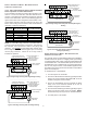
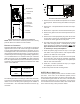
Air Handler Integrated
Control Module
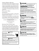
Typical Single-Stage Cool,
Single-Stage Heat Thermostat
Dehumidistat
[Optional]
Remote Condensing Unit
(Single-Stage AC)
NEU
HOT
12RCG
W1 Y1 Y2
O
DEHUM
RCG
W1 Y1
RC
Y
Place Jumper Between Y1
and O for Proper
Dehumidification Operation
and Proper Ramping
Profile Operation
W2
Typical Single-Stage Cooling with Single-Stage Heating
______________________________________
Air Handler Integrated
Control Module
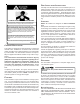
Typical Two-Stage Cool,
Two-Stage Heat Thermostat
Dehumidistat
[Optional]
Remote Condensing Unit
(Two-Stage AC)
NEU
HOT
12RCG
W1 W2 Y1 Y2
O
DEHUM
RCG
W1 W2 Y1 Y2
RC
Y1 Y2
Place Jumper Between Y1
and O for Proper
Dehumidification Operation
and Proper Ramping
Profile Operation
Typical Two-Stage Cooling with Two-Stage Heating
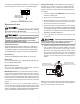
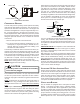
12RC
A
ir Handler
Integrated Control Module
Typical Single-Stage Cool,
Single-Stage Heat
Heat Pump Thermostat
Dehumidistat
[Optional]
G
W1 W2 Y1 Y2
O
DEHUM
Remote Condensing Unit
(Single-Stage HP)
NEU
HOT
W/E
RCG
Y1
O
RC
W1 Y
O
Typical Single-Stage Heat Pump with Auxiliary/Emergency
Heating
______________________________________
12RC
A
ir Handler
Integrated Control Module
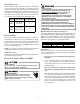
Typical Two-Stage Cool,
Two-Stage Heat
Heat Pump Thermostat
Dehumidistat
[Optional]
G
W1 W2 Y1 Y2
O
DEHUM
Remote Condensing Unit
(Two-Stage HP)
NEU
HOT
W/E
RCG
W2 Y1 Y2
O
RC
W1 Y1 Y2
O
Typical Two Stage Heat Pump heating and Auxiliary/
Emergency Heating
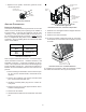
24 VOLT DEHUMIDISTAT WIRING - NON-COMMUNICATING
THERMOSTAT CONNECTIONS
The optional usage of a dehumidistat allows the air handler’s
circulator blower to operate at a slightly lower speed during
a combined thermostat call for cooling and dehumidistat call
for dehumidification. This lower blower speed enhances de-
humidification of the conditioned air as it passes through the
AC coil. For proper function, a dehumidistat applied to this
air handler must operate on 24 VAC and utilize a switch which
opens on humidity rise.
To install/connect a dehumidistat:
1. Turn OFF power to air handler.
2. Secure the dehumidistat neutral wire (typically the white
lead) to the screw terminal marked “DEHUM” on the air
handler’s integrated control module.
3. Secure the dehumidistat hot wire (typically the black
lead) to the screw terminal marked “R” on the air
handler’s integrated control module.
4. Secure the dehumidistat ground wire (typically the green
lead) to the ground screw on the air handler. NOTE:
Ground wire may not be present on all dehumidistats.
5. Turn ON power to air handler.