
Install Instructions
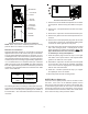

5
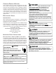
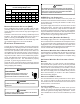
10 15 20 25 30 35 40 45
14 75 50 37 NR NR NR NR NR
12 118795947NRNRNRNR
10 188 125 95 75 63 54 NR NR
8 301 201 150 120 100 86 75 68
6 471 314 235 188 157 134 118 110
*Based on NEC 1996
Maximum Allowable Length in Feet
to Limit Voltage Drop to 2%*
Minimum Circuit Ampacity (MCA)
Wire Size
(AWG)
MAXIMUM OVERCURRENT PROTECTION (MOP)
Every installation must include an NEC (USA) or CEC
(Canada) approved overcurrent protection device. Also,
check with local or state codes for any special regional re-
quirements.
Protection can be in the form of fusing or HACR style circuit
breakers. The Series and Rating Plate can be used as a
guide for selecting the MAXIMUM overcurrent device.
NOTE: Fuses or circuit breakers are to be sized larger than
the equipment MCA but not to exceed the MOP.
E
LECTRICAL
C
ONNECTIONS
Consult the local power company and local codes before
installing this unit. All wiring must be in accordance with the
National Electrical Code as well as all local codes. Knock-
outs have been provided on side and top of the cabinet for
the installation of the electrical conduit. If the knockouts on
the cabinet sides are used for electrical conduit, an adapter
ring must be used in order to meet UL1995 safety require-
ments. Use Minimum Circuit Ampacity and type of wire to
determine proper wire size. The unit MUST be properly
grounded. A ground lug is provided in the unit.
Check all factory connections before connecting electrical
power to unit to ensure none were loosened or disconnected
during shipping and handling.
HIGHVOLTAGE!
T
O
PREVENT
PERSONAL
INJURY
OR
DEATH
DUE
TO
ELECT RICAL
SHOCK
,
DISCONNECT
THE
ELECT RICAL
POWER
BEFORE
ELECTRICALLY
CONNECTING
THE
UNIT
.
WARNING
T
O
AVOID
THE
RISK
OF
FIRE
OR
EQUIPM ENT
DAMAGE
,
USE
COPPER
CONDUCTORS
.
WARNING
T
O
AVOID
THE
RISK
OF
PERSONAL
INJURY
,
WIRING
TO
THE
UNIT
MUST
BE
PROPERLY
POLA RIZED
AND
GROUNDED
.
CAUTION
A
LL
WIRING
MUST
COMPLY
WITH
APPLICABLE
LOCAL
AND
NATIONAL
CODES
.T
YPE
AND
LOCATION
OF
FUSED
DISCONNECT
SWITCH
(
ES
)
MUST
COMPLY
WITH
ALL
APPLICABLE
CODES
AND
PROVIDE
OVERCURRENT
PROTECTION
AS
SHOW N
ON
THE
NAMEPLATE
.
WARNING
208/230 VOLT LINE CONNECTIONS
If heater kits will not be installed, remove the proper size
knockout for the electrical conduit connection. Connect elec-
trical conduit to the unit using two washers to make an ap-
proved connection.
The power supply wires must be connected to the red and
black power wiring. Two wire nuts are provided in the bag
assembly for this connection. Wrap the wire nuts with elec-
trical tape. (Insulated crimp type connectors, field supplied,
may be substituted for the wire nuts and electrical tape pro-
vided proper size connectors are used.) A ground wire MUST
be connected to the ground lug inside the unit.
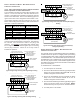
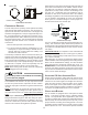
AIR HANDLER ONLY (NON-HEAT KIT MODELS)
The building supply connects to the stripped black and red
wires contained in the air handler electrical compartment cav-
ity. A ground screw is also contained in this area. Attach the
supply wires to the air handler conductors as shown in the
unit wiring diagram using appropriately sized solderless con-
nectors or other NEC or CEC approved means.
AIR HANDLER WITH NON-CIRCUIT BREAKER HEAT KITS
A terminal block is provided with the HKR kit to attach the
power supply and air handler connections. Follow the HKR
Installation Manual and wiring diagram for complete wiring
details.
AIR HANDLER WITH HEAT KITS CONTAINING A CIRCUIT
BREAKER
HKR models with a “C” suffix contain a circuit breaker(s).
The air handler has a plastic cover on the access panel that
will require either one or both sections to be removed to al-
low the heat kit circuit breaker(s) to be installed. See the
HKR Installation Instructions for further details. The air han-
dler wires and supply wires are installed directly onto the
HKR circuit breaker(s) as shown in the HKR Installation
Manual and wiring diagram.
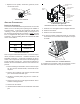
OPERATION ON 208 VOLT SUPPLY
The unit transformer is factory connected for 240 V opera-
tion. If unit is to operate on 208 V, disconnect the red wire
from terminal 3 of the unit transformer and connect them to
terminal 2 of the unit transformer.
LOW VOLTAGE WIRING
Low voltage wiring connections are made at the top of the
cabinet. See the 24 Volt Thermostat Wiring section of this
manual for typical low voltage wiring connections. A mini-
mum 18 AWG wire must be used for installations up to 100
feet.