
Install Instructions

4
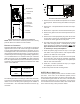
RETURN AIR FILTERS
Each installation must include a return air filter. This filtering
may be performed at the air handler or externally such as a
return air filter grille. Air handlers mounted in the downflow
orientation, including “B” series, require external filtering. A
washable filter is available as an accessory. To ensure opti-
mum performance frequent filter cleaning is advised. Refer
to Air Filter Accessory table for the appropriate filter.
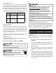
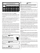
AVPTC Filter Number Qty Required
1830
FIL 36-42
(19" x 21")
1
3137
4260
FIL 48-61
(21-1/2" x 23")
1
Air Filter Accessories
E
LECTRIC
H
EAT
Refer to this manual in combination with the instructions pro-
vided with the heat kit for the correct installation procedure.
The air handlers listed in this manual do not have factory
installed electric heat. Electric heat is available as an ac-
cessory. If installing this option, the ONLY heat kits that can
be used are the HKR series.
NOTE: The Amana
®
brand EHK, ECB, EDB, and EDK kits
are NOT approved for use with these air handlers.
HKR INSTALLATION
Follow instructions listed in Installation and Operating Instruc-
tions shipped with the heat kit.
E
LECTRICAL
S
UPPLY
W
IRE
AND
MOP
FIRE HAZARD!
To avoid the risk of property damage, personal injury
or fire, use only copper conductors.
HIGH VOLTAGE!
Failure to do so may cause property damage,
personal injury or death.
Disconnect ALL power before servicing.
Multiple power sources may be present.
HIGH VOLTAGE!
To avoid property damage, personal injury or death
due to electrical shock, this unit MUST have an
electrical ground. The
electrical ground circuit may consist of an
appropriately sized electrical wire connecting the
ground lug in the unit control box to the building
electrical service panel.
Other methods of grounding are permitted if performed
in accordance with the National Electric Code
(NEC)/American National Standards Institute
(ANSI)/National Fire Protection Association (NFPA) 70
and local/state codes. In Canada, electrical grounding
is to be in accordance with the Canadian Electric Code
(CSA) C22.1.
uninterrupted, unbroken
BUILDING ELECTRICAL SERVICE INSPECTION
This unit is designed for single-phase electrical supply. DO
NOT OPERATE ON A THREE-PHASE POWER SUPPLY.
Measure the power supply to the unit. The supply voltage
must be in agreement with the unit nameplate power re-
quirements and within the range specified below.
Nominal Input Minimum Voltage Maximum Voltage
208/240 187 253
Power Supply Voltage
WIRE SIZING
Wire size is important to the operation of your equipment.
Use the following check list when selecting the appropriate
wire size for your unit.
• Wire size must carry the Minimum Circuit Ampac-
ity (MCA).
• Refer to the NEC (USA) or CSA (Canada) for wire
sizing. The unit MCA for the air handler and the op-
tional electric heat kit can be found on the unit Series
and Rating Plate.
• Wire size allows for no more than a 2% voltage
drop from the building breaker/fuse panel to the
unit.
Refer to the latest edition of the National Electric Code
or in Canada the Canadian Electric Code when deter-
mining the correct wire size. The following table shows
the current carrying capabilities for copper conductors
rated at 75
o
C with a 2% voltage drop. Use the table
below to determine the voltage drop per foot of vari-
ous conductors.