
Install Instructions

3
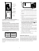
CARBON MONOXIDE POISONING HAZARD
-
Special Warning for Installation of Furnace or Air Handling Units in
Enclosed Areas such as Garages, Utility Rooms or Parking Areas
Carbon monoxide producing devices (such as an automobile, space
heater, gas water heater, etc.) should not be operated in enclosed areas
such as unventilated garages, utility rooms or parking areas because of
the danger of carbon monoxide (CO) poisoning resulting from the exhaust
emissions. If a furnace or air handler is installed in an enclosed area such
as a garage, utility room or parking area and a carbon monoxide producing
device is operated therein, there must be adequate, direct outside
ventilation.
This ventilation is necessary to avoid the danger of CO poisoning which
can occur if a carbon monoxide producing device continues to operate in
the enclosed area. Carbon monoxide emissions can be (re)circulated
throughout the structure if the furnace or air handler is operating in any
mode.
CO can cause serious illness including permanent brain damage or death.
B10259-216
C
ODES
& R
EGULATIONS
This product is designed and manufactured to comply with
national codes. Installation in accordance with such codes
and/or prevailing local codes/regulations is the responsibil-
ity of the installer. The manufacturer assumes no responsi-
bility for equipment installed in violation of any codes or regu-
lations.
The United States Environmental Protection Agency
(EPA) has issued various regulations regarding the in-
troduction and disposal of refrigerants. Failure to fol-
low these regulations may harm the environment and
can lead to the imposition of substantial fines. Should
you have any questions please contact the local office of the
EPA.
If replacing an air handler, the system must be manufac-
turer approved and Air Conditioning, Heating and Refrigera-
tion Institute (AHRI) matched. NOTE: Installation of un-
matched systems is strongly discouraged.
F
EATURES
This air handler is a part of the ComfortNet™ family of prod-
ucts. It may be installed as part of a “non-communicating”
system using a standard 24 VAC thermostat. However, with
the CTK0*AA ComfortNet thermostat kit, this air handler may
be installed as part of a digitally communicating system. The
ComfortNet system provides automatic airflow configuration,
enhanced setup features, and enhanced diagnostics. It also
reduces the number of thermostat wires to a maximum of
four and a minimum of two.
P
RE
-I
NSTALLATION
I
NSTRUCTIONS
Carefully read all instructions for the installation prior to in-
stalling product. Make sure each step or procedure is un-
derstood and any special considerations are taken into ac-
count before starting installation. Assemble all tools, hard-
ware and supplies needed to complete the installation. Some
items may need to be purchased locally. Make sure every-
thing needed to install the product is on hand before start-
ing.
L
OCATION
NOTE: Air handlers are designed for indoor installation
only.
Give special consideration to minimizing the length of refrig-
erant tubing when installing air handlers. Refer to Remote
Cooling/Heat Pump Service Manual TP-107 Long Line Set
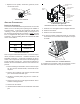
Application R-410A for guidelines. The unit clearance from
a combustible surface may be 0". However, service clear-
ance is to take precedence. In addition allow a minimum of
24" in front of the unit for service clearance.
If the unit is located in an area with high ambient tempera-
ture and/or high humidity, the air handler may be subject to
nuisance sweating of the casing. On these installations, a
wrap of 2” fiberglass insulation with a vapor barrier is rec-
ommended.
Do not install the air handler in a location that violates the
instructions provided with the condenser.
Consult all appropriate regulatory codes prior to determin-
ing final clearances. When installing this unit in an area that
may become wet, elevate the unit with a sturdy, non-porous
material. In installations that may lead to physical damage
(i.e. a garage) it is advised to install a protective barrier to
prevent such damage.
D
UCTWORK
This air handler is designed for a complete supply and re-
turn ductwork system.
Do not operate this product without all the ductwork
attached.
To ensure correct system performance, the ductwork is to
be sized to accommodate 375-425 CFM per ton of cooling
with the static pressure not to exceed .5" WC. Inadequate
duct work that restricts airflow can result in improper perfor-
mance and compressor or heater failure. Ductwork is to be
constructed in a manner that limits restrictions and main-
tains suitable air velocity. Ductwork is to be sealed to the
unit in a manner that will prevent leakage.
RETURN DUCTWORK
DO NOT TERMINATE THE RETURN DUCTWORK IN AN
AREA THAT CAN INTRODUCE TOXIC, OR OBJECTION-
ABLE FUMES/ODORS INTO THE DUCTWORK. The re-
turn ductwork is to be introduced into the air handler bottom
(upflow configuration).