
Install Instructions


16
12RC
12RC
CTK0*AA
Thermostat
ComfortNet
Air Handler Integrated
Control Module
Compatible
ComfortNet
AC/HP Integrated
Control Module
Compatible
Optional
40VA Transformer
(included in
CTK0*AA kit)
208/230 VAC
24 VAC
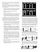
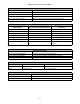
12RC
System Wiring using Two-Wires between Air Handler and
AC/HP and Four-Wires between Air Handler and Thermostat
COMFORTNET™ SYSTEM ADVANCED FEATURES
Refer to the communicating thermostat installation manual
for information on accessing advanced features and menus.
DIAGNOSTICS
Accessing the air handler’s diagnostics menu provides ready
access to the last six faults detected by the air handler. Faults
are stored most recent to least recent. Any consecutively
repeated fault is stored a maximum of three times. Example:
A clogged return air filter causes the air handler’s motor to
repeatedly enter a limiting condition. The control will only
store this fault the first three consecutive times the fault oc-
curs. Navigate to the diagnostics menu as described above
in Accessing and Navigating the Advanced Features Menus.
NOTE: It is highly recommended that the fault history be
cleared when performing maintenance or servicing the air
handler.
NETWORK TROUBLESHOOTING
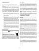
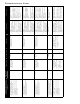
NOTE: Indoor Unit BIAS and TERMINATION Dipswitches
are factory set and should not be changed.
S1
S2
ONOFF
S3
BIAS
BIAS
TERM
Dipswitches - Indoor Unit BIAS and TERMINATION
The ComfortNet system is a fully communicating system,
and thus, constitutes a network. Occasionally the need to
troubleshoot the network may arise. The integrated air han-
dler control has some on-board tools that may be used to
troubleshoot the network. These tools are: red communica-
tions LED, green receive (Rx) LED, and learn button. Refer
to the Communications Troubleshooting Chart at the end of
this manual for error codes, possible causes and corrective
actions
• Red communications LED – Indicates the status of
the network. The table below indicates the LED sta-
tus and the corresponding potential problem.
• Green receive LED – Indicates network traffic. The
table below indicates the LED status and the corre-
sponding potential problem.
• Learn button – Used to reset the network. Depress
the button for approximately 2 seconds to reset the
network.
SYSTEM TROUBLESHOOTING
NOTE: Refer to the instructions accompanying the
ComfortNet compatible outdoor AC/HP unit for
troubleshooting information.
Refer to the Troubleshooting Chart at the end of this manual
for a listing of possible air handler error codes, possible
causes and corrective actions.
S
TART
-U
P
P
ROCEDURE
• Prior to start-up, ensure that all electrical connections
are properly sized and tightened.
• All panels must be in place and secured. For Air Tight
application, neoprene gasket must be positioned at
prescribed locations to achieve 2% leakage.
• Tubing must be leak free.
• Unit should be elevated, trapped and pitched to allow
for drainage.
• Low voltage wiring is connected.
• Auxiliary drain is installed when necessary and pitched
to allow for drainage.
• Drain pan and drain tubing has been leak checked.
• Return and supply ducts are sealed.
• Unit is elevated when installed in a garage or where
flammable vapors may be present.
• Unit is protected from vehicular or other physical dam-
age.
• Return air is not obtained from any areas where there
may be objectionable odors, flammable vapors or prod-
ucts of combustion such as carbon monoxide (CO),
which may cause serious personal injury or death.