
Install Instructions


13
NOTE: For installations not indicated in the preceding
Temperature Rise Tables, the following formula is to be used:
TR = (kW x 3412) x (Voltage Correction) x (1.08 x CFM)
Where: TR = Temperature Rise
kW = Heater Kit Actual kW
3412 = Btu per kW
Voltage Correction =.96 (230 Supply Volts)
=.92 (220 Supply Volts)
=.87 (208 Supply Volts)
1.08 = Constant
CFM = Measured Airflow
NOTE: The Temperature Rise Tables can also be used to
determine the air handler airflow delivery. When using these
tables for this purpose set the room thermostat to maximum
heat and allow the system to reach steady state conditions.
Insert two thermometers, one in the return air and one in the
supply air. The temperature rise is the supply air temperature
minus the room air temperature.
Use HKR specification sheets to determine the HKR avail-
able for a given air handler.
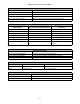
MODELS HKR-03* HKR-05*/-05C* HKR-06* HKR-08*/-08C* HKR-10*/-10C* HKR-15C HKR-20C HKR-21C
AVPTC183014A* X X X X1 X1 --- --- ---
AVPTC313714A* X X X X1 X1 X2 --- ---
AVPTC426014A* X X X X X X X3 X3
Heat Kit Selection
* Revision level that may or may not be designated.
C Circuit breaker option.
NOTE:
When 8kW and 10kW heat kits are used with an AVPTC1830 and AVPTC3137, matched with 2- ton outdoor unit, see Note 1 below.
1
Set Heater Kit dip switches 9, 10 and 11 to 6kW setting (9-ON, 10-OFF,11-ON) to obtain 840 CFM.
2
This heater kit can only be used for ‘1000 CFM or higher’ applications.
3
This heater kit can only be used for ‘1200 CFM or higher’ applications.
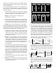
NOTE: Airflow blink codes are approximations of actual airflow.
Profiles 5 6
AOFFOFF
BONOFF
COFFON
DONON
30 sec/50% 7.5 mins/82% 30 sec/50%
------- 30 sec/50% 60 sec/100%
------- 7.5 mins/82% 60 sec/100%
Profile
Select io n
Switches
Pre-Run Short-Run Off Delay
------- ------- 60 sec/100%
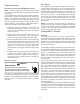
Tap 1 2
TRIM
34
AOFFOFF
0%
OFF OFF
BONOFF
+ 10%
ON OFF
COFFON
- 10%
OFF ON
DONON
0%
ON ON
Adjust
Selection
Switches
Cool
Selection
Switches
Speed Selection Dip Switches
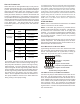
TO SET AIRFLOW:
1.Select appropriate model from Cooling/Heat Pump Airflow Table.
Based on desired Airflow for your application select corresponding tap
(A,B,C or D). Set dip switches 1 & 2 to the appropriate ON/OFF
positions.
2. Select appropriate Airflow adjustment factor for application
(0%. +10%, -10%). Set dip switches 3 & 4 to the appropriate ON/OFF
positions.
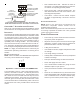
3.
If installed with Heater Kit:
Using Electric Heat Airflow Table, set dip switches 9, 10 and 11 to the
appropriate ON/OFF positions based on Heater kit installed.
If installed without Heater Kit:
Ensure dip switches 9, 10 and 11 are set to a valid heater kit selection.
Example: The only valid heater kits for AVPTC183014* applications
are 3, 5, 6, 8 and 10 kW.
Failure to do so will result in a Heater Kit error code.
TO SET COMFORT MODE:
Select desired Comfort Mode profile (see profiles above). Set switches
5 and 6 to the appropriate ON/OFF positions.
Tap
Low
Stage
Cool
High
Stage
Cool
A 420 630
B 560 840
C 700 1040
A 410 610
B 560 830
C 700 1040
D 830 1240
A 810 1210
B 940 1410
C10501560
D12101800
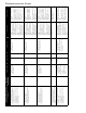
Htr kW 9 10 11
AVPTC
183014*
AVPTC
313714*
AVPTC
426014*
3 ONONON630610600
5 ON ON OFF 730 710 680
6 ON OFF ON 840 840 790
8 ON OFF OFF 1080 1060 990
10 OFF ON ON 1270 1260 1190
15 OFF ON OFF NR 1470 1390
20 OFF OFF ON NR NR 1580
21 OFF OFF OFF NR NR 1580
NOTE: Airflow data shown applies to the emergency heat m ode (electric heat onl y) in either n on-
communicating mode operation or fully communicating mode operation.
Cooling/Heat Pump Airflow Table
Electric Heat Airflow Table
NOTE: Airflow data shown applies to non-communicating mode operation only. For a fully
communicating system, please see the outdoor unit's install ation instructions for cooling and heat
pump airflow data. See ComfortNet™ System - Airflow Consideration section for details.
Model
AVPTC183014*
AVPTC313714*
AVPTC426014*