
Install Instructions


11
adjusted by the installer to match the installation require-
ments so as to provide the correct electric heating CFM and
correct cooling CFM.
Use the CFM LED (green), adjacent to the integrated con-
trol module electric heat connector to obtain an approximate
airflow quantity. The green CFM LED blinks once for each
100 CFM of airflow.
1. Determine the tonnage of the cooling system installed
with the air handler. If the cooling capacity is in BTU/hr
divide it by 12,000 to convert capacity to TONs.
Example: Cooling Capacity of 30,000 BTU/hr.
30,000/12,000 = 2.5 Tons
2. Determine the proper air flow for the cooling system.
Most cooling systems are designed to work with air flows
between 350 and 450 CFM per ton. Most manufactur-
ers recommend an air flow of about 400 CFM per ton.
Example: 2.5 tons X 400 CFM per ton = 1000 CFM
The cooling system manufacturer’s instructions must be
checked for required air flow. Any electronic air cleaners or
other devices may require a specific airflow; consult installa-
tion instructions of those devices for requirements.
3. Knowing the air handler model, locate the high stage
cooling air flow charts in the Specification Sheet appli-
cable to your model. Look up the cooling air flow de-
termined in step 2 and find the required cooling speed
and adjustment setting.
Example: An AVPTC183014 air handler installed with
a 2.5 ton air conditioning system. The air flow needed
is 1000 CFM. Looking at the cooling speed chart for
AVPTC183014, find the air flow closest to 1000 CFM.
A cooling airflow of 1000 CFM can be attained by set-
ting the cooling speed to “C” and the adjustment to “0”
(no adjustment).
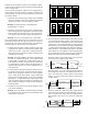
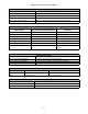
4. Locate the blower speed selection DIP switches on the
integrated control module. Select the desired “cooling”
speed tap by positioning switches 1 and 2 appropri-
ately. Select the desired “adjust” tap by positioning
switches 3 and 4 appropriately. Refer to the following
Dipswitches - Cooling Airflow and Airflow Adjust Taps
figure for switch positions and their corresponding taps.
Verify CFM by counting the number of times the green
CFM LED blinks.
5. Continuous fan speed is 30% of the air handler’s maxi-
mum airflow capability.
Example: If the air handler’s maximum airflow capabil-
ity is 2000 CFM, the continuous fan speed will be 0.30
x 2000 CFM = 600 CFM.
S1
S2
S1
S2
S1
S2
S1
S2
OFF OFF OFF OFFON ON ON ON
Tap A Tap B
Cooling Air flow Speed Tap (*indicates factory setting)
Tap C Tap D*
S3
S4
Normal* +10%
Air flow Adjust Taps (*indicates factory setting)
-10% Normal
OFF OFF OFF OFFON ON ON ON
S3
S4
S3
S4
S3
S4
Dipswitches - Cooling Airflow and Airflow Adjust Taps
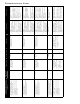
6. The multi-speed circulator blower also offers several
custom ON/OFF ramping profiles. These profiles may
be used to enhance cooling performance and increase
comfort level. The ramping profiles are selected using
DIP switches 5 and 6. Refer to the following Dipswitches
- Cooling Airflow Ramping Profiles figure for switch po-
sitions and their corresponding taps. Refer to the bullet
points below for a description of each ramping profile.
Verify profile selection by counting the green CFM LED
blinks and timing each step of the ramping profile.
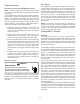
• Profile A provides only an OFF delay of one (1) minute
at 100% of the cooling demand airflow.
OFF
100% CFM 100% CFM
1 min
OFF
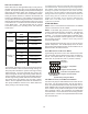
• Profile B ramps up to full cooling demand airflow by
first stepping up to 50% of the full demand for 30 sec-
onds. The motor then ramps to 100% of the required
airflow. A one (1) minute OFF delay at 100% of the
cooling airflow.
50% CFM
1/2 min
100% CFM
100% CFM
1 min
OFF
OFF
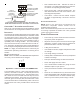
• Profile C ramps up to 82% of the full cooling demand
airflow and operates there for approximately 7 1/2 min-
utes. The motor then steps up to the full demand air-
flow. Profile C also has a one (1) minute 100% OFF
delay.
100% CFM
OFF
OFF