
User Guide
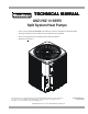
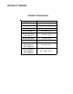
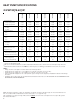
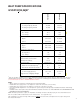
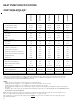

HEAT PUMP SPECIFICATIONS
7
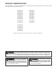
NOTE: This data is provided as a guide, it is important to electrically connect the unit and properly size fuses/circuit breakers and
wires in accordance with all national and/or local electrical codes. Use copper wire only.
Unit specifications are subject to change without notice. ALWAYS refer to the unit's serial plate for the most up-to-date general
and electrical information.
*SZ130241B
*SZ130361B
Nominal Capacities
Cooling Capacity, BTUH 24,000 36,000
Heating Capacity, BTUH 23,000 34,000
Compressor
R.L. Amps 12.8 16.7
L.R. Amps 58.3 79.0
Low Pressure Switch
Open 22 PSIG 22 PSIG
Close 50 PSIG 50 PSIG
High Pressure Switch
Open 610 PSIG 610 PSIG
Close 420 PSIG 420 PSIG
Condenser Fan Motor
Horsepower 1/6 1/4
F.L. Amps 1.10 1.50
Liquid Line, Inches O.D.* 3/8" 3/8"
Suction Line, Inches O.D.* 3/4" 3/4"
Refrigerant Charge 113.0 131.0
Power Supply 208/230-60-1 208/230-60-1
Minimum Circuit Ampacity
(1)
17.1 22.3
Maximum Overcurrent Device
(2)
25 35
Electrical Conduit Size
Power Supply (Inches) 1/2 or 3/4 1/2 or 3/4
Approximate Shipping W eight 162 182
G/VSZ130[24,36]B*
(1)
Wire size should be determined in accordance with National Electrical Codes; extensive wire runs will require larger wire sizes.
(2)
Maximum Overcurrent Protection Device: MUST use Time Delay Fuse or HACR type Circuit Breaker of the same size as noted.
(3)
Tested and rated in accordance with AHRI Standard 210/240
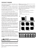
NOTES:
• Always check the S & R plate for electrical data on the unit being installed.
• Installer will need to supply 7/8" to 1-1/8" adapters for suction line connections (4 & 5 ton units).
• Installer will need to supply 3/4" to 7/8" adapters for suction line connections (3 ton unit).
• Unit is charged with refrigerant for 15' of 3/8" liquid line. System charge must be adjusted per Installation Instructions Final Charge
Procedure.
• Installation of these units requires the specified TXV Kit to be installed on the indoor coil. THE SPECIFIED TXV IS DETERMINED BY THE
OUTDOOR UNIT, NOT THE INDOOR COIL.