INSTALLATION & OPERATING INSTRUCTIONS for GPG13 SINGLE PACKAGE GAS-ELECTRIC HEATING & COOLING UNIT Affix this manual and Users Information Manual adjacent to the unit. ® C US This Forced Air Central Unit Design Complies With Requirements Embodied in The American National Standard / National Standard of Canada Shown Below. ANSI Z21.47•CSA-2.3 Central Furnaces RECOGNIZE THIS SYMBOL AS A SAFETY PRECAUTION.
INDEX Replacement Parts ............................................................................................................................................................. 3 ORDERING PARTS .............................................................................................................................................. 3 Safety Instructions ...................................................................................................................................................
REPLACEMENT PARTS WARNING ORDERING PARTS THIS PRODUCT CONTAINS OR PRODUCES A CHEMICAL OR CHEMICALS WHICH When reporting shortages or damages, or ordering repair parts, give the complete unit model and serial numbers as stamped on the unit’s nameplate. MAY CAUSE SERIOUS ILLNESS OR DEATH AND WHICH ARE KNOWN TO THE STATE OF CALIFORNIA TO CAUSE CANCER, BIRTH DEFECTS OR OTHER REPRODUCTIVE HARM. Replacement parts for this appliance are available through your contractor or local distributor.
• • • CARBON MONOXIDE POISONING HAZARD Special Warning for Installation of Furnaces or Air Handling Units in Enclosed Areas such as Garages, Utility Rooms or Parking Areas Carbon monoxide producing devices (such as an automobile, space heater, gas water heater, etc.) should not be operated in enclosed areas such as unventilated garages, utility rooms or parking areas because of the danger of carbon monoxide (CO) poisoning resulting from the exhaust emissions.
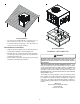
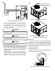
Rooftop Installation • • The unit may be installed directly on wood floors or on Class A, Class B, or Class C roof covering material. To avoid possible personal injury, a safe, flat surface for service personnel should be provided. ROOF CURB INSTALLATIONS ONLY: • • • Roof Curb Installation Sufficient structural support must be determined prior to locating and mounting the curb and package unit. Ductwork must be constructed using industry guidelines.
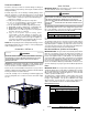
TRANSPORTATION DAMAGE GAS PIPING Check the carton upon arrival for external damage. If damage is found, a request for inspection by carrier agent should be made in writing immediately. IMPORTANT NOTE: This unit is factory set to operate on natural gas at the altitudes shown on the rating plate. Carefully inspect the unit for damage including damage to the cabinetry. Any bolts or screws which may have loosened in transit must be re-tightened. In the event of damage, the receiver should: 1.
GAS PIPING CHECKS Refer to the Proper Piping Practice drawing for the general layout at the unit. The following rules apply: 1. Use black iron pipe and fittings for the supply piping. The use of a flex connector and/or copper piping is permitted as long as it is in agreement with local codes. 2. Use pipe joint compound on male threads only. Pipe joint compound must be resistant to the action of the fuel used. 3. Use ground joint unions. 4.
TANKS AND PIPING WARNING Complete information regarding tank sizing for vaporization, recommended regulator settings and pipe sizing is available from most regulator manufacturers and propane gas suppliers. Since propane gas will quickly dissolve white lead or most standard commercial compounds, special pipe dope must be used. Shellac base compounds resistant to the actions of liquefied petroleum gases such as Gasolac®, Stalactic®, Clyde’s® or John Crane® are satisfactory.
Note:Junction box location shown is optional and is for illustration purposes only. B18099-18 L2 HEAT COOL 1068-83-400A L2 K4 JUNCTION BOX FS 3 1 1 2 2 2 5 5 4 1 4 4 7 3 6 9 6 6 9 12 12 9 8 7 11 11 10 8 10 11 12 10 7 Y W G P1 R 3 K1 ECON F1 FUSE 3 AMP MAX BREAK FOR TWO STAGE COMPRESSOR 120 135 P3 150 P2 SPEED-UP LOW VOLTAGE CONNECTOR K2 ANSI Z21.20 AUTOMATIC IGNITION SYSTEM 24VAC 50/60Hz 400mA MAX.
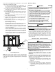
Down Discharge Applications Cut insulation around bottom openings and remove panels from the bottom of the unit, saving the screws holding the panels in place. NOTE: Single phase models require installation of horizontal duct kit #20464501PDGK (medium chassis) and #20464502PDGK (large chassis). Y/Y2 G Y R W From Unit DUCTWORK Y/Y2 R W Y1 G Duct systems and register sizes must be properly designed for the C.F.M. and external static pressure rating of the unit.
3. The 30-second HEAT FAN ON delay time begins. *PG13(48,60)***1A ONLY: Heat on delay begins when thermostat calls for heat. ECM motor is energized approximately 45 seconds later. NOTE: ECM motor may operate at approximately 100 CFM or less during the 45 second on delay period. ECM motor will energize at heating speed after the 45 second delay regardless of the status of the main burner flame. 4. The unit delivers heat to the conditioned space until the thermostat is satisfied. 5. The gas valve deenergizes.
NOTE: A 180-second anti-short cycle is integral to the control and prevents recycling of the compressor. Rollout Protection FAN ONLY 1. Thermostat calls for FAN ONLY by energizing “G”. 2. Approximately seven seconds later, the indoor fan starts. 3. The indoor fan continues to run for approximately 60 seconds after “G” is de-energized. *PG13(48,60)***1A ONLY: 1. Thermostat calls for FAN ONLY by energizing “G”. 2.
9. 10. 11. 12. If having waited for five minutes and no gas smell is noted, move the gas control valve switch to the ON position. Replace the heat exchanger door on the side of the unit. Open the manual gas valve external to the unit. Turn on the electrical power supply to the unit. Set the thermostat to desired setting.
Main Burner Flame Check (switches 1 and 2) provides airflow adjustment for heating airflow. The “COOL” adjustment function (switches 5 and 6) provides airflow adjustments for cooling airflow. The “ADJUST” function (switches 7 and 8) will adjust the heating AND cooling airflow +10% or - 15%. The “DELAY” function (switches 3 and 4) is not field adjustable.
Dehumidification COOLING STARTUP The GE ECM motor has the capability to provide increased dehumidification during cooling operation. This is accomplished by lowering the airflow to approximately 85% of the nominal cooling airflow. Example: Unit is operating at 1400 CFM and humidistat calls for dehumidification. Resulting airflow is 0.85* 1400 CFM = 1190 CFM. To make use of this feature, a 24VAC humidistat which opens on humidity rise is required.
ABNORMAL OPERATION - HEATING Pressure Switch Stuck Open A pressure switch stuck open can be caused by a faulty pressure switch, faulty wiring, a disconnected or damaged hose, a blocked or restricted flue, or a faulty induced draft blower. If the control senses an open pressure switch during the prepurge cycle, the induced draft blower only will be energized.
MAINTENANCE CLEAN OUTSIDE COIL (QUALIFIED SERVICER ONLY) The coil with the outside air flowing over it should be inspected annually and cleaned as frequently as necessary to keep the finned areas free of lint, hair and debris. CONDENSER, EVAPORATOR, AND INDUCED DRAFT MOTORS Bearings on the air circulating blower motor, condenser motor and the combustion fan motor are permanently lubricated. No additional oiling is required.
MAIN BURNER FLAME (QUALIFIED SERVICER ONLY) CAUTION Flames should be stable, soft and blue (dust may cause orange tips but must not be yellow). The flames must extend directly outward from the burner without curling, floating or lifting off. LABEL ALL WIRES PRIOR TO DISCONNECTION WHEN SERVICING CONTROLS. WIRING ERRORS CAN CAUSE IMPROPER AND DANGEROUS OPERATION. CAUTION ALWAYS VERIFY PROPER OPERATION AFTER SERVICING. For further information on the yearly inspection, consult the User Manual.
IGNITION Light Signal Off 1 Flash 2 Flashes 3 Flashes 4 Flashes 5 Flashes 6 Flashes CONTROL DIAGNOSTIC Gas Valve CHART Refer to Abnormal Heating or Cooling Operation Sections of this Manual Internal Control Failure External Lockout Pressure Switch Stuck Open Pressure Switch Stuck Closed Thermal Protection Device Open Flame Detected with Gas Valve Closed Short Cycle Compressor Delay (Cooling Only) HEATING TIMING Circulator Blower INDICATOR CHART 100 % 50 % On Off On Off Igniter On Off Induced D
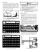
APPENDIX UNIT DIMENSIONS 47 51 18 7/16 16 FLUE EXHAUST 1 3/8 C A 5 1/2 16 7 15/16 B 2 3/4 SUCTION/LIQUID PRESSURE PORTS BEHIND COMPRESSOR ACCESS PANEL RETURN B HEAT EXCHANGE ACCESS PANEL 4 3/4 GAS SUPPLY ENTRANCE CONDENSATE DRAIN CONNECTION 3/4" NPT FEMALE SUPPLY 3 EVAPORATOR/CONTROL PANEL ACCESS PANEL 16 1/8 19 1/8 OF ER Y NT VIT E C RA G 7 5/16 DIMENSION DIMENSION INCHES 7 7/8 20 (INCHES) A B 24 C POWER WIRE ENTRANCE A B C MEDIUM LARGE SMALL MEDIUM LARGE 27 16 7 1/2 32 16 32
GPG13(24,30,36,42)1A WIRING DIAGRAM P HIGH VOLTAGE! DISCONNECT ALL POWER BEFORE SERVICING OR INSTALLING THIS UNIT. MULTIPLE POWER SOURCES MAY BE PRESENT. FAILURE TO DO SO MAY CAUSE PROPERTY DAMAGE, PERSONAL INJURY OR DEATH.
GPG13(24,30,36,42)1A WIRING DIAGRAM HIGH VOLTAGE! DISCONNECT ALL POWER BEFORE SERVICING OR INSTALLING THIS UNIT. MULTIPLE POWER SOURCES MAY BE PRESENT. FAILURE TO DO SO MAY CAUSE PROPERTY DAMAGE, PERSONAL INJURY OR DEATH. B4312003 REV. B Wiring is subject to change. Always refer to the wiring diagram on the unit for the most up-to-date wiring.
GPG13(48)1A WIRING DIAGRAM HIGH VOLTAGE! DISCONNECT ALL POWER BEFORE SERVICING OR INSTALLING THIS UNIT. MULTIPLE POWER SOURCES MAY BE PRESENT. FAILURE TO DO SO MAY CAUSE PROPERTY DAMAGE, PERSONAL INJURY OR DEATH.
GPG13(48)1A WIRING DIAGRAM HIGH VOLTAGE! DISCONNECT ALL POWER BEFORE SERVICING OR INSTALLING THIS UNIT. MULTIPLE POWER SOURCES MAY BE PRESENT. FAILURE TO DO SO MAY CAUSE PROPERTY DAMAGE, PERSONAL INJURY OR DEATH.
GPG13(60)1A WIRING DIAGRAM HIGH VOLTAGE! DISCONNECT ALL POWER BEFORE SERVICING OR INSTALLING THIS UNIT. MULTIPLE POWER SOURCES MAY BE PRESENT. FAILURE TO DO SO MAY CAUSE PROPERTY DAMAGE, PERSONAL INJURY OR DEATH.
GPG13(60)1A WIRING DIAGRAM HIGH VOLTAGE! DISCONNECT ALL POWER BEFORE SERVICING OR INSTALLING THIS UNIT. MULTIPLE POWER SOURCES MAY BE PRESENT. FAILURE TO DO SO MAY CAUSE PROPERTY DAMAGE, PERSONAL INJURY OR DEATH.
GPG13(36)3A WIRING DIAGRAM HIGH VOLTAGE! DISCONNECT ALL POWER BEFORE SERVICING OR INSTALLING THIS UNIT. MULTIPLE POWER SOURCES MAY BE PRESENT. FAILURE TO DO SO MAY CAUSE PROPERTY DAMAGE, PERSONAL INJURY OR DEATH.
GPG13(36)3A WIRING DIAGRAM HIGH VOLTAGE! DISCONNECT ALL POWER BEFORE SERVICING OR INSTALLING THIS UNIT. MULTIPLE POWER SOURCES MAY BE PRESENT. FAILURE TO DO SO MAY CAUSE PROPERTY DAMAGE, PERSONAL INJURY OR DEATH.
GPG13(48,60)3A WIRING DIAGRAM HIGH VOLTAGE! DISCONNECT ALL POWER BEFORE SERVICING OR INSTALLING THIS UNIT. MULTIPLE POWER SOURCES MAY BE PRESENT. FAILURE TO DO SO MAY CAUSE PROPERTY DAMAGE, PERSONAL INJURY OR DEATH.
GPG13(48,60)3A WIRING DIAGRAM HIGH VOLTAGE! DISCONNECT ALL POWER BEFORE SERVICING OR INSTALLING THIS UNIT. MULTIPLE POWER SOURCES MAY BE PRESENT. FAILURE TO DO SO MAY CAUSE PROPERTY DAMAGE, PERSONAL INJURY OR DEATH.
GPG13(36)4A WIRING DIAGRAM HIGH VOLTAGE! DISCONNECT ALL POWER BEFORE SERVICING OR INSTALLING THIS UNIT. MULTIPLE POWER SOURCES MAY BE PRESENT. FAILURE TO DO SO MAY CAUSE PROPERTY DAMAGE, PERSONAL INJURY OR DEATH.
GPG13(36)4A WIRING DIAGRAM HIGH VOLTAGE! DISCONNECT ALL POWER BEFORE SERVICING OR INSTALLING THIS UNIT. MULTIPLE POWER SOURCES MAY BE PRESENT. FAILURE TO DO SO MAY CAUSE PROPERTY DAMAGE, PERSONAL INJURY OR DEATH.
GPG13(48,60)4A WIRING DIAGRAM HIGH VOLTAGE! DISCONNECT ALL POWER BEFORE SERVICING OR INSTALLING THIS UNIT. MULTIPLE POWER SOURCES MAY BE PRESENT. FAILURE TO DO SO MAY CAUSE PROPERTY DAMAGE, PERSONAL INJURY OR DEATH.
GPG13(48,60)4A WIRING DIAGRAM HIGH VOLTAGE! DISCONNECT ALL POWER BEFORE SERVICING OR INSTALLING THIS UNIT. MULTIPLE POWER SOURCES MAY BE PRESENT. FAILURE TO DO SO MAY CAUSE PROPERTY DAMAGE, PERSONAL INJURY OR DEATH.
GPG13(48,60)1B WIRING DIAGRAM HIGH VOLTAGE! DISCONNECT ALL POWER BEFORE SERVICING OR INSTALLING THIS UNIT. MULTIPLE POWER SOURCES MAY BE PRESENT. FAILURE TO DO SO MAY CAUSE PROPERTY DAMAGE, PERSONAL INJURY OR DEATH.
GPG13(48,60)1B WIRING DIAGRAM HIGH VOLTAGE! DISCONNECT ALL POWER BEFORE SERVICING OR INSTALLING THIS UNIT. MULTIPLE POWER SOURCES MAY BE PRESENT. FAILURE TO DO SO MAY CAUSE PROPERTY DAMAGE, PERSONAL INJURY OR DEATH.
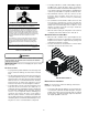
MINIMUM CLEARANCES 48" MIN 12" MIN 3" MIN . 12" MIN 36" MIN (FOR SERVICE) NOTE: Roof overhang should be no more than 36". UNIT Min.
THIS PAGE LEFT BLANK INTENTIONALLY 38
THIS PAGE LEFT BLANK INTENTIONALLY 39
NOTE: SPECIFICATIONS AND PERFORMANCE DATA LISTED HEREIN ARE SUBJECT TO CHANGE WITHOUT NOTICE Quality Makes the Difference! All of our systems are designed and manufactured with the same high quality standards regardless of size or efficiency. We have designed these units to significantly reduce the most frequent causes of product failure. They are simple to service and forgiving to operate. We use quality materials and components. Finally, every unit is run tested before it leaves the factory.