INSTALLATION INSTRUCTIONS FOR *MVM96 & *CVM96 MODULATING GAS FURNACE (Type FSP CATEGORY IV Direct or Non Direct Vent Air Furnace) Installer: Affix all manuals adjacent to the unit. These furnaces comply with requirements embodied in the American National Standard / National Standard of Canada ANSI Z21.47·CSA-2.3 Gas Fired Central Furnaces. ® C US RECOGNIZE THIS SYMBOL AS A SAFETY PRECAUTION.
TABLE OF CONTENTS SHIPPING INSPECTION ....................................................................................................................................... 6 ELECTROSTATIC DISCHARGE (ESD) PRECAUTIONS ................................................................................................ 6 TO THE INSTALLER ..........................................................................................................................................
GAS SUPPLY AND PIPING .............................................................................................................................. 29 HIGH ALTITUDE DERATE .................................................................................................................................. 29 PROPANE GAS CONVERSION ........................................................................................................................... 29 GAS PIPING CONNECTIONS ................................
TROUBLESHOOTING ..................................................................................................................................... 50 ELECTROSTATIC DISCHARGE (ESD) PRECAUTIONS .............................................................................................. 50 DIAGNOSTIC CHART ....................................................................................................................................... 50 RESETTING FROM LOCKOUT ........................................
Adhere to the following warnings and cautions when installing, adjusting, altering, servicing, or operating the furnace. To ensure proper installation and operation, thoroughly read this manual for specifics pertaining to the installation and application of this product. WARNING WARNING TO PREVENT POSSIBLE PROPERTY DAMAGE, PERSONAL INJURY OR DEATH DUE TO ELECTRICAL SHOCK , THE FURNACE MUST BE LOCATED TO PROTECT THE ELECTRICAL COMPONENTS FROM WATER.
4. Discharge your body to ground before removing a new control from its container. Follow steps 1 through 3 if installing the control on a furnace. Return any old or new controls to their containers before touching any ungrounded object. SHIPPINGINSPECTION All units are securely packed in shipping containers tested according to International Safe Transit Association specifications. The carton must be checked upon arrival for external damage.
In such applications, the furnace must be installed with the following stipulations: • It must be installed per the installation instructions provided and per local and national codes. • It must be installed indoors in a building constructed on site. • It must be part of a ducted system and not used in a free air delivery application. • It must not be used as a “make-up” air unit.
• All furnace operating conditions (including ignition, input rate, temperature rise and venting) are verified according to these installation instructions. WARNING POSSIBLE PROPERTY DAMAGE, PERSONAL INJURY OR DEATH DUE TO FIRE, EXPLOSION, SMOKE, SOOT, CONDENSATION, ELECTRICAL SHOCK NOTE: The Commonwealth of Massachusetts requires that the following additional requirements must also be met: • Gas furnaces must be installed by a licensed plumber or gas fitter. • A T-handle gas cock must be used.
• • • • • • • • deicing salts or chemicals carbon tetrachloride halogen type refrigerants cleaning solutions (such as perchloroethylene) printing inks paint removers varnishes hydrochloric acid cements and glues antistatic fabric softeners for clothes dryers and masonry acid washing materials Seal off a non-direct vent furnace if it is installed near an area frequently contaminated by any of the above substances. This protects the non-direct vent furnace from airborne contaminants.
3. As far as practical, close all building doors and windows and all doors between the space in which the appliance(s) connected to the venting system are located and other spaces of the building. COMBUSTION & VENTILATION AIR REQUIREMENTS WARNING TO AVOID PROPERTY DAMAGE, PERSONAL INJURY OR DEATH, 4. Close fireplace dampers. SUFFICIENT FRESH AIR FOR PROPER COMBUSTION AND VENTILATION OF FLUE GASES MUST BE SUPPLIED. MOST HOMES REQUIRE OUTSIDE AIR BE 5.
LEVELING Leveling ensures proper condensate drainage from the heat exchanger and induced draft blower. For proper flue pipe drainage, the furnace must be level lengthwise from end to end. The furnace should also be level from back to front or have a slight tilt with the access doors downhill (approximately 3/4 inches) from the back panel. The slight tilt allows the heat exchanger condensate, generated in the recuperator coil, to flow forward to the recuperator coil front cover.
Kit Orifice Hig h Stage Low Stage Pr essure Switch Change None #45 1 3.5" w.c. 1" w.c. None LPKMOD** *** 1.25MM 2 10.0" w.c . 2.6" w.c. None Manifo ld Pressure Gas Altitude Natural 0-7000 Propane NOTE: In Canada, gas furnaces are only certified to 4500 feet.
It is the responsibility of the installer to follow the manufacturers’ recommendations and to verify that all vent/flue piping and connectors are compatible with furnace flue products. Additionally, it is the responsibility of the installer to ensure that all piping and connections possess adequate structural integrity and support to prevent flue pipe separation, shifting, or sagging during furnace operation.
• • A vent termination shall not terminate over public walkways or over an area where condensate or vapor could create a nuisance or hazard or could be detrimental to the operation of regulators, relief valves, or other equipment. The combustion air intake termination of a direct vent application should not terminate in an area which is frequently dusty or dirty.
3. Upflow and Counterflow units. Remove the vent/flue pipe from the furnace. 4. Cut the vent/flue pipe 3.75 inches from the flanged end of the pipe (see “Vent/Flue Pipe Cuts” figure). The section of pipe attached to the coupling will reach through the side panel to the induced draft blower. Discard remaining pipe and elbows. Counterflow units. Cut the vent/flue pipe 3.75 inches from the blower deck coupling (see “Vent/Flue Pipe Cuts” figure).
3. Remove plastic plug from alternate combustion air intake location. Relocate and install plug in standard air intake location (basepan). Plug the remaining hole in the blower deck with the plastic plug included in the drain kit bag. 4. With the gasket facing the cabinet side panel, and the flange’s flat spot facing forward, secure the combustion air intake coupling to the cabinet using the screws removed in step 1 or with field-supplied 3/8” #8 self -drilling screws. 8. Upflow and Counterflow units.
6. For direct vent installations, secure field-supplied combustion air intake pipe directly to the air intake coupling. NOTE: A PVC coupling or elbow is required on counterflow units. COUNTERFLOW Non-Direct Vent (Single Pipe) (1)(2) Maximum Allowable Length of Vent/Flue Pipe (ft) Unit Input NON-DIRECT VENT (SINGLE PIPE) PIPING 60,000 Non-direct vent installations require only a vent/flue pipe.
In a basement installation, the vent/flue pipe can be run between joist spaces. If the vent pipe must go below a joist and then up into the last joist space to penetrate the header, two 45° elbows should be used to reach the header rather than two 90° elbows. DIRECT VENT (DUAL PIPE) PIPING The inlet air screens provided in the installation instruction packet are available for the installer to use in the inlet of the combustion air pipe to prevent animals from building nests in the combustion air pipe.
Horizontal terminations should be as shown in the following figure. Refer to Vent/Flue Pipe and Combustion Pipe - Termination Location for location restrictions. A 2 3/8” diameter wall penetration is required for 2” diameter pipe. A 3” diameter hole is required for a 2 1/2” pipe and a 3 1/2” diameter hole is required for 3” diameter pipe.
SIDE WALL VENT KIT This kit is to be used with 2” or 3” direct vent systems. The vent kit must terminate outside the structure and may be installed with the intake and exhaust pipes located side-by-side or with one pipe above the other. This kit is NOT intended for use with single pipe (indirect vent) installations. Refer to the directions furnished with the Side Wall Vent Kit (p/n 0170K00000S) for installation specifications.
STANDARD RIGHT OR LEFT SIDE DRAIN HOSE CONNECTIONS UPRIGHT INSTALLATIONS-TRAP ON RIGHT SIDE All installations positions require the use of the drain trap, hoses, tubes, and clamps. The following quantity of hoses, tubes, and hose clamps are provided with the unit. In a upright installation drain hoses are connected to drain ports on the rubber elbow and the recuperator coil front cover.
ALTERNATE VENT/FLUE DRAIN HOSE CONNECTIONS Upright installations using the alternate vent/flue outlet will require “right-side only” drain hoses to be connected as follows. Refer to Vent/Flue Pipe and Combustion Air Pipe for details on alternate vent/flue pipe connection. 1. Remove the rubber plug/cap from the right-side drain port on the front cover . Save for use in step 3. 2. Secure Hose A to front cover drain port with a red hose clamp. Route hose to rear right side panel grommet hole. 3.
5. Cut “X” inches from the long end of Hose B and discard. Refer to table for appropriate length to cut. Secure remaining hose to Tube 1 with a green hose clamp. Route other end of Hose B to front left side panel grommet hole. UPRIGHT INSTALLATIONS-TRAP ON LEFT SIDE NOTE: For left side trap installation, grommets must be moved to the left side of the furnace and the plugs installed on the right side of the furnace. 1. Remove the rubber plug/cap from the left side drain port on the front cover. 2.
2. Secure Hose A to front cover drain tap with a red hose clamp. Route hose to rear right (down) side panel grommet holes. 3. Cut 1/4 inch from the end of the drain port on the rubber elbow and discard. 4. Insert Tube 1 into rubber elbow drain port and secure with a silver hose clamp. Angle tube outward toward front of furnace. 5. Cut 17 3/4 inches from the long end of Hose B and discard. 6. Secure remaining end of Hose B to exposed end of Tube 1 with a green hose clamp.
Horizontal installations with the left side panel down will require drain hoses to be connected to the left side front cover drain port and the side drain port on the rubber elbow. 7. Insert approximately one inch of each Tube 2 through left side panel grommet hole. Secure tubes to Hose A and Hose B with a green hose clamps. NOTE: Tube must reach bottom of trap. Ensure hoses and tubes maintain a downward slope for proper drainage and that they are not kinked or binding. 1.
Line polarity must be observed when making field connections. Line voltage connections can be made through either the right or left side panel. The furnace is shipped configured for a right side (left side for counterflows) electrical connection with the junction box located inside the burner compartment. To make electrical connections through the opposite side of the furnace, the junction box must be relocated to the other side of the burner compartment prior to making electrical connections.
To ensure proper unit grounding, the ground wire should run from the furnace ground screw located inside the furnace junction box all the way back to the electrical panel. NOTE: Do not use gas piping as an electrical ground. To confirm proper unit grounding, turn off the electrical power and perform the following check. 1. Measure resistance between the neutral (white) connection and one of the burners. 2. Resistance should measure 10 ohms or less.
Y2 W1 W2 Y2 W1 W2 Once the switch is set, the dehumidify function is enabled during a combination call for cooling (T-Stat) and dehumidification (DEHUMStat). Refer to the dip switch chart in the back section of this manual. Furnace Integrated Control Module FOSSIL FUEL APPLICATIONS NEU Y2 This furnace can be used in conjunction with a heat pump in a fossil fuel application.
CAUTION TO PREVENT UNRELIABLE OPERATION OR EQUIPMENT DAMAGE, THE INLET GAS SUPPLY PRESSURE MUST BE AS SPECIFIED ON THE UNIT RATING PLATE WITH ALL OTHER HOUSEHOLD GAS FIRED APPLIANCES NEUTRAL OPERATING. L1 Inlet gas supply pressures must be maintained within the ranges specified in the following table. The supply pressure must be constant and available with all other household gas fired appliances operating. The minimum gas supply pressure must be maintained to prevent unreliable ignition.
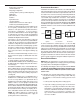
The following stipulations apply when connecting gas piping. Refer to Gas Piping Connections figure for typical gas line connections to the furnace. GAS VALVE This unit is equipped with a 24 volt gas valve which modulates by pneumatic linkage to the combustion air blower Taps for measuring the gas supply pressure and manifold pressure are provided on the valve. This is a non-convertible gas valve equipped for natural gas.
GAS VALVE MANIFOLD MANUAL SHUT OFF VALVE (UPSTREAM FROM BURNERS GAS LINE PIPE UNION) PLUG IN GAS LINE HOLE PLUG IN ALTERNATE GAS LINE HOLE HEIGHT REQUIRED BY LOCAL CODE GROMMET IN STANDARD GAS LINE HOLE GAS VALVE PIPE UNION DRIP LEG BURNERS DRIP LEG MANUAL SHUT-OFF VALVE (UPSTREAM FROM GROUND JOINT PIPE UNION) GROUND JOINT PIPE UNION DRIP LEG GAS VALVE GAS VALVE GROMMET IN STANDARD GAS LINE HOLE BURNERS BURNERS DRAIN TRAP DRAIN TRAP MANIFOLD MANIFOLD ALTERNATE GAS LINE LOCATION ALTERNATE GA
DIRECT/STANDARD INLET PIPING PROPANE GAS TANKS AND PIPING WARNING WARNING IF THE GAS FURNACE IS INSTALLED IN A BASEMENT, AN EXCAVATED AREA OR CONFINED SPACE , IT IS STRONGLY RECOMMENDED TO EDGES OF SHEET METAL HOLES MAY BE SHARP. USE GLOVES AS A PRECAUTION WHEN REMOVING HOLE PLUGS. CONTACT A PROPANE SUPPLIER TO INSTALL A GAS DETECTING WARNING DEVICE IN CASE OF A GAS LEAK.
A closed return duct system must be used, with the return duct connected to the furnace. NOTE: Ductwork must never be attached to the back of the furnace. For upflow installations requiring 1800 CFM or more, use either two side returns or bottom return or a combination of side /bottom. Flexible joints may be used for supply and return connections to reduce noise transmission.
When the furnace is used in connection with a cooling unit, the furnace should be installed in parallel with or on the upstream side of the cooling unit to avoid condensation in the heating element. With a parallel flow arrangement, the dampers or other means used to control the flow of air must be adequate to prevent chilled air from entering the furnace and, if manually operated, must be equipped with means to prevent operation of either unit unless the damper is in the full heat or cool position.
FILTER ACCESS DOOR 1000 1200 1400 1600 2000 0603__XA --- --- 564* 564* 672 768 0805__XA --- --- --- 752* 752* 768 960 1005__XA 1155__XA --- --- --- 940* 940* 940* 960 RETURN DUCT CENTRAL RETURN GRILLE FILTER SUPPORT BRACKET COUNTERFLOW COOLING AIRFLOW REQUIREMENT (CFM) Input Airflow (Field Supplied) 600 800 1000 1200 1400 1600 2000 0604__XA --- --- 641* 641* 672 768 --- 0805__XA 1005__XA --- --- --- 854* 854* 854* 960 *Minimum filter area dictated by
• • • • After 2 minutes, the IFC increases to 57% at a rate of 1% per second After 10 total minutes, the IFC increases to 78% at a rate of 1% per second. After 20 total minutes, the IFC increases to 100% at a rate of 1% per second for the remainder of the call for heat. The circulator is adjusted to the appropriate CFM, corresponding to the current firing rate. IGNITION Call for 2nd-Stage Heat - Thermostat contacts close R to W1 and W2.
• • • If the differential is equal to or less than 2 degrees, the IFC will follow the conventional 2-Stage algorithm, equivalent to a W1 request and be reflected in the Heat Current Demand Status %. If the heat differential is greater than 2 degrees, the IFC will follow the conventional 2-Stage algorithm, equivalent to a W2 request and be reflected in the Heat Current Demand Status %. The circulator will operate per the heat airflow profile. FURNACE STARTUP 1. 2. 3. 4.
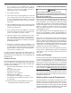
PS CONNECTION the normal firing rate sequence at a rate of 100% for 5 minutes or until the end of the call for heat. The display will show the normal “Hi” while the control is firing at 100%. If the Fault Recall Push-Button has not been pressed within 5 seconds of displaying “Ft” the display will revert back to normal. ATMOSPHERE PORT FLOW DIRECTION 4. Measure furnace gas supply pressure with burners firing. Supply pressure must be within the range specified in the Inlet Gas Supply Pressure table.
3. Outlet pressure tap connections: Remove the outlet pressure boss plug. Install an 1/8" NPT hose barb fitting into the outlet pressure tap. 4. Attach a hose and manometer to the outlet pressure barb fitting. 5. Turn ON the gas supply. 6. Turn on power and close thermostat “R” and “W1” contacts to provide a call for low stage heat.
4. Adjust temperature rise by adjusting the circulator blower speed. Increase blower speed to reduce temperature rise. Decrease blower speed to increase temperature rise. Refer to Startup Procedure and Adjustment -Circulator Blower Speeds for speed changing details. The cooling system manufacturer’s instructions must be checked for required air flow. Any electronic air cleaners or other devices may require specific air flows, consult installation instructions of those devices for requirements. 3.
• Profile A provides only an OFF delay of one (1) minute at 100% of the cooling demand airflow. 100% CFM Model 100% CFM OFF OFF *CVM960604CX* 1 min • Profile B ramps up to full cooling demand airflow by first stepping up to 50% of the full demand for 30 seconds. The motor then ramps to 100% of the required airflow. A one (1) minute OFF delay at 100% of the cooling airflow is provided.
Two-way digital communications is accomplished using only two wires. The thermostat and subsystem controls are powered with 24 VAC. Thus, a maximum of 4 wires between the equipment and thermostat is all that is required to operate the system. BLOWER HEAT OFF DELAY TIMINGS The integrated control module provides a selectable heat off delay function. The heat off delay period may be set to 90, 120, 150, 180 seconds using the DIP switches or jumper provided on the control module.
In continuous fan mode, the CTK0*AA thermostat provides the airflow demand. The thermostat may be configured for one of threecontinuous fan speed settings allow for 25%, 50% or 75% airflow, based on the furnaces’ maximum airflow capability. During continuous fan operation, the thermostat sends a fan request along with the continuous fan demand to the furnace. The furnace, in turn, sends the demand to the ECM motor. The ECM motor delivers the requested continuous fan airflow.
Pull Down Pull Up Bias Dehum Compressor T-Stat Heat Heat Off Delay Adjust Taps Cooling Ramping Continuous Fan Speed Tap Heating Speed Tap Cooling Speed Tap Purpose A B C D A B C D A B C D A B C D 0 Trim Adjust Plus 10% Minus 10% 0 Trim Adjust 90 Seconds 120 Seconds 150 Seconds 180 Seconds 1 Stage Stat 2 Stage Stat 1-Stage Compressor 2-Stage Compressor Disabled Enabled Disabled Enabled Disabled Enabled Disabled Enabled Function ------------------- ------------------- --- --- 2 OFF OFF
FOSSIL FUEL APPLICATIONS NOTE: Use of the CTK0*AA transformer is recommended if installing a dual fuel/fossil fuel system. Failure to use the transformer in the outdoor unit could result in over loading of the furnace transformer. This furnace can be used in conjunction with a ComfortNet™ compatible heat pump in a fossil fuel application.
FURNACE ADVANCED FEATURES MENUS CONFIGURATION Submenu Item Number of Heat Stages (HT STG) Input Rate (BTU/HR) Motor HP (1/2, ¾, or 1 MTR HP) Indication (for Display Only; not User Modifiable) Displays the number of furnace heating stages Displays the furnace input rate in kBtu/hr Displays the furnace indoor blower motor horsepower DIAGNOSTICS Submenu Item Fault 1 (FAULT #1) Indication/User Modifiable Options Most recent furnace fault Comments For display only Fault 2 (FAULT #2) Next most recent furnac
NON-COMM (APPLIES ONLY TO A COMMUNICATING COMPATIBLE FURNACE MATCHED WITH A NON-COMMUNICATING COMPATIBLE SINGLE STAGE AIR CONDITIONER) Submenu Item Cool Airflow (CL CFM) User Modifiable Options 18, 24, 30, 36, 42, 48, or 60, default is 18 Cool Airflow Trim (CL TRM) -10% to +10% in 2% increments, default is 0% Cool Airflow Profile (CL PRFL) A, B, C, or D, default is A Cool ON Delay (CL ON) 5, 10, 20, or 30 seconds, default is 5 seconds Cool OFF Delay (CL OFF) 30, 60, 90, or 120 seconds, default is 3
LED LED Status Off 1 Flash Indication Possible Causes Notes & Cautions • None • Communications Failure • None • Depress Learn Button • Verify that pull up, pull down and bias dip switches are in the ON position. • None • Depress once quickly for a power-up reset • Depress and hold for 2 seconds for an out-of-box reset.
• If the last call for heat was a call for high heat, the air circulating motor will run on the high heating speed for thirty (30) seconds and then switch to the low heating speed for the balance of the heat off delay period (60, 90, 120 or 150 seconds). Circulator blower and electronic air cleaner terminal is deenergized. OPERATIONAL CHECKS The burner flames should be inspected with the burner compartment door installed.
PRESSURESWITCHES DIAGNOSTIC CHART The pressure switches are normally-open (closed during operation) negative air pressure-activated switches. They monitor the airflow (combustion air and flue products) through the heat exchanger via pressure taps located on the induced draft blower and the coil front cover. These switches guard against insufficient airflow (combustion air and flue products) through the heat exchanger and/or blocked condensate drain conditions.
ANNUALINSPECTION HORIZONTAL UNIT FILTER REMOVAL The furnace should be inspected by a qualified installer, or service agency at least once per year. This check should be performed at the beginning of the heating season. This will ensure that all furnace components are in proper working order and that the heating system functions appropriately. Pay particular attention to the following items. Repair or service as necessary.
Functional Parts ListGas Valve Gas Manifold Natural Gas Orifice Propane Gas Orifice Igniter Flame Sensor Rollout Limit Switch Primary Limit Switch Auxiliary Limit Switch Pressure Switch Induced Draft Blower Door Switch BEFORE LEAVING AN INSTALLATION • Cycle the furnace with the thermostat at least three times. • Verify cooling and fan only operation. Review the Owner’s Manual with the homeowner and discuss proper furnace operation and maintenance. • Leave literature packet near furnace.
x Furnace fails to operate. x Integrated control module LED display provides E1 error code. x ComfortNet thermostat “Call for Service” icon illuminated. x ComfortNet thermostat scrolls “Check Furnace” message. x Induced draft blower runs continuously with no further furnace operation. x Integrated control module LED display provides E2 error code. x ComfortNet thermostat “Call for Service” icon illuminated. x ComfortNet thermostat scrolls “Check Furnace” message.
x Furnace fails to operate. x Integrated control module LED display provides E7 error code. x ComfortNet thermostat “Call for Service” icon illuminated. x ComfortNet thermostat scrolls “Check Furnace” message. x Open Fuse x Flame sense micro amp signal is low x Problem with igniter circuit. E6 E7 x Manual reset rollout switch is open Ed x No furnace operation. x Integrated control module LED display provides Ed error code. E5 x Open auxiliary input. EF x No furnace operation.
EA d0 REVERSED PLTY NO NET DATA x Polarity of 115 volt AC is reversed x Data not yet on network. EA d0 E9 x Furnace fails to operate. x Integrated control module LED display provides EA error code. x ComfortNet thermostat “Call for Service” icon illuminated. x ComfortNet thermostat scrolls “Check Furnace” message. x Furnace fails to operate. x Integrated control module LED display provides d0 error code. x ComfortNet thermostat “Call for Service” icon illuminated.
b0 b1 b2 b3 x Furnace fails to operate. x Integrated control module LED display provides b1 error code. x ComfortNet thermostat “Call for Service” icon illuminated. x ComfortNet thermostat scrolls “Check Furnace” message. x Furnace fails to operate. x Integrated control module LED display provides b2 error code. x ComfortNet thermostat “Call for Service” icon illuminated. x ComfortNet thermostat scrolls “Check Furnace” message. x Furnace operates at reduced performance.
x Furnace fails to operate. x Integrated control module LED display provides b7 error code. x ComfortNet thermostat “Call for Service” icon illuminated. x ComfortNet thermostat scrolls “Check Furnace” message. x Furnace operates at reduced performance or operates on low stage when high stage is expected. x Integrated control module LED display provides b9 error code. x Furnace fails to operate. x Integrated control module LED display provides b5 error code.
STATUS CODES INTERNAL CONTROL FAULT/NO POWER O n E 0 NORMAL OPERATION E 1 E 2 LOW STAGE PRESSUE SWITCH STUCK CLOSED AT START OF HEATING CYCLE E E E E E E E E OPEN HIGH LIMIT SWITCH 3 4 5 6 7 8 9 A LOCKOUT DUE TO EXCESSIVE RETRIES LOW STAGE PRSSURE SWITCH STUCK OPEN FLAME DETECTED WHEN NO FLAME SHOULD BE PRESENT OPEN FUSE LOW FLAME SIGNAL IGNITER FAULT OR IMPROPER GROUNDING HIGH STAGE PRESSURE SWITCH STUCK CLOSED AT START OF HEATING CYCLE HIGH STAGE PRSSURE SWITCH STUCK OPEN REVERSED 115 VAC POLARI
WIRING DIAGRAM *MVM96_A*, *CVM96_A* ID BLOW ER TW O -STA GE PRES SURE SW ITCH AS SEMBLY HOT SURFA CE IGNITER BR LOW FIRE P RE SSURE C HIGH FIRE PRESSURE S W ITCH C NO SW ITCH W ARNING:DISCONNECT PO W ER BE FO RE SERVICING W IRING . TO UNIT MUST BE PROPE RLY POLA RIZED AND GROUNDED.
5151 San Felipe Suite 500 Houston, TX 77056 www.goodmanmfg.com • www.amana-hac.com © 2011 Goodman Manufacturing Company, L.P.