GKS9 GAS-FIRED WARM AIR FURNACE INSTALLATION INSTRUCTIONS This furnace is shipped from the factory as a Dedicated Upflow. A “Blocked Drain Kit” is available and MUST BE USED if the furnace is installed Horizontal Left or Horizontal Right. Check the Serial/Rating Plate on the furnace for the Kit part number. Installer: Affix all manuals adjacent to the unit.
Table of Contents I. Component Identification ............................................................................................................................................... 5 II. Safety .............................................................................................................................................................................. 6 ELECTROSTATIC DISCHARGE (ESD) PRECAUTIONS .........................................................................................
Table of Contents XIV. Startup Procedure & Adjustment ............................................................................................................................. 28 HEAT ANTICIPATOR SETTING ................................................................................................................................ 28 DRAIN TRAP PRIMING .......................................................................................................................................
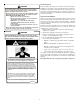
TO THE INSTALLER WARNING Before installing this unit, please read this manual thoroughly to familiarize yourself with specific items which must be adhered to, including but not limited to: unit maximum external static pressure, gas pressures, BTU input rating, proper electrical connections, circulating air temperature rise, minimum or maximum CFM, and motor speed connections.
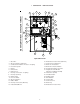
I.
If you come in contact with an ungrounded object, repeat step 2 before touching control or wires. 4. Discharge your body to ground before removing a new control from its container. Follow steps 1 through 3 if installing the control on a furnace. Return any old or new controls to their containers before touching any ungrounded object. II. SAFETY Please adhere to the following warnings and cautions when installing, adjusting, altering, servicing, or operating the furnace.
• • NOTE: Do not connect the temporary duct directly to the furnace. The duct must be sized according to the instructions under Section V, Combustion and Ventilation Air Requirements, Section 5.3.3. The furnace heat exchanger, components, duct system, air filters and evaporator coils are thoroughly cleaned following final construction clean up. All furnace operating conditions (including ignition, input rate, temperature rise and venting) are verified according to these installation instructions. IV.
• • • • cements and glues antistatic fabric softeners for clothes dryers and masonry acid washing materials Seal off a non-direct vent furnace if it is installed near an area frequently contaminated by any of the above substances. This protects the non-direct vent furnace from airborne contaminants. To ensure that the enclosed non-direct vent furnace has an adequate supply of combustion air, vent from a nearby uncontaminated room or from outdoors.
If resizing is required on any portion of the venting system, use the appropriate table in Appendix G in the latest edition of the National Fuel Gas Code ANSI Z223.1 and/or CSA B149.1-05 Installation Codes. THERMOSTAT LOCATION The thermostat should be placed approximately five feet from the floor on a vibration-free, inside wall in an area having good air circulation.
space shall be considered in making this determination. Each opening shall have a minimum free area of 1 square inch per 1,000 BTU per hour of the total input rating of all gas utilization equipment in the confined space, but not less than 100 square inches. One opening shall be within 12 inches of the top and one within 12 inches of the bottom of the enclosure.
FURNACE MUST BE LEVEL 5. When directly communicating with the outdoors, the single opening shall have a minimum free area of 1 square inch per 3,000 BTU per hour of total input rating of all equipment in the enclosure. FROM END TO END ALTERNATE VENT/FLUE FURNACE MUST BE LEVEL LOCATION OR SLIGHTLY TILTED FORWARD WITH THE DOORS 0" - 3/4" BELOW THE BACK PANEL 5.3.4 Specially Engineered Installations: 4 3/4" MINIMUM The requirements of 5.3.
AIR DISCHARGE change to compensate for the energy content difference between natural and propane gas. High altitude installations may require both a pressure switch and an orifice change. These changes are necessary to compensate for the natural reduction in the density of both the gas fuel and the combustion air at higher altitude. For installations above 7000 feet, please refer to your distributor for required kit(s).
responsibility of the installer to ensure that all piping and connections possess adequate structural integrity and support to prevent flue pipe separation, shifting, or sagging during furnace operation. insulated with 1/2” thick closed cell foam. Also all vent/flue piping exposed outdoors in excess of the terminations shown in this manual (or in unheated areas) should be insulated with 1/2” thick closed cell foam. Inspect piping for leaks prior to installing insulation.
NOTE: In Canada, the Canadian Fuel Gas Code takes precedence over the preceding termination restrictions. NOTE: For non-direct vent installations, a minimum of one 90° elbow should be installed on the combustion air intake coupling to guard against inadvertent blockage. CANADIAN VENTING REQUIREMENTS COMBUSTION AIR PIPE In Canada, venting must conform to the requirements of the current CAN/CSA-B149.1-05 Installation Code.
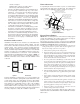
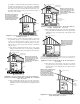
NON-DIRECT VENT (SINGLE PIPE) PIPING FLANGE 3.75" CUT HERE Vent/Flue Pipe Cuts 5. Remove plastic plug from alternate vent/flue location. Relocate and install plug in standard vent/flue location (top cover). 6. Insert cut section of vent/flue pipe and coupling into alternate vent/flue location. Using a rubber coupling and worm gear hose clamps from the drain kit bag, attach the vent/flue pipe and coupling to the induced draft blower.
restrictions. The penetration of the vent through the roof must be sealed tight with proper flashing such as is used with a plastic plumbing vent. Horizontal vent/flue pipe terminations should be as shown in the following figure. Refer to Section IX, Vent/Flue Pipe and Combustion Air Pipe - Termination Locations for details concerning location restrictions. A 2 3/8” diameter wall penetration is required for 2” diameter pipe.
Horizontal terminations should be as shown in the following figure. Refer to Section IX, Vent/Flue Pipe and Combustion Pipe Termination Location for location restrictions. A 2 3/8” diameter wall penetration is required for 2” diameter pipe. A 3” diameter hole is required for a 2 1/2” pipe and a 3 1/2” diameter hole is required for 3” diameter pipe.
The condensate which is generated must be piped to an appropriate drain location. In upright installations, the furnace’s drain hoses may exit either the right or left side of the furnace. NOTE: If the alternate vent/flue outlet is utilized in an upright installation, the drain trap and drain connections must be located on the same side as the alternate vent/flue outlet.
2. Secure Hose A to front cover drain port with a red hose clamp. Route hose to rear side panel grommet hole. Left side drains Cut “X” inches from the long end of Hose B and discard. Refer to table for appropriate length to cut. Secure remaining hose to Tube 1 with a green hose clamp. Route other end of Hose B to front left side panel grommet hole. NOTE: For left side drainage, grommets will have to be relocated to left side panel. 3.
6. Insert short end of each Tube 2 through side panel grommet holes. Secure tubes to Hose A and Hose B with green hose clamps. Ensure hoses and tubes maintain a downward slope for proper drainage and that they are not kinked or binding. For details concerning mounting of the drain trap, refer to Section X, Condensate Drain Lines and Drain Trap - Upright Drain Trap Mounting. 6. Cut 17 7/8 inches from the long end of Hose B and discard. 7.
HORIZONTAL INSTALLATIONS NOTE: This furnace is shipped from the factory as a Dedicated Upflow. A “Blocked Drain Kit” is available and MUST BE USED if the NOTE: This furnace is shipped from the factory as a Dedicated furnace is installed Horizontal Left or Horizontal Right. Check the Upflow. A “Blocked Drain Kit” is available and MUST BE USED if the Serial/ Rating Plate on the furnace for the Kit P/N. furnace is installed Horizontal Left or Horizontal Right.
4. Insert Tube 1 into rubber elbow drain port and secure with a silver hose clamp. Angle tube outward toward front of furnace. 5. Cut 17 3/4 inches from the long end (end opposite the bend) of Hose B. Save the part with the bend and discard the 17 3/4 inch piece that was cut. 6. Secure remaining end of Hose B to exposed end of Tube 1 with a green hose clamp. Route hose to front right down side panel grommet holes. 7. Cut 5 1/2 inches straight length from the long end (end with taper) of each Tube 2.
with the furnace must be replaced, it must be replaced with wiring material having a temperature rating of at least 105°C. Any replacement wiring must be copper conductor. * * * 115 VOLT LINE CONNECTIONS * * Connect hot, neutral, and ground wires as shown in the wiring diagram located on the unit’s blower door.
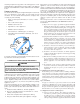
gas conversion kit. Taps for measuring the gas supply pressure and manifold pressure are provided on the valve. The gas valve has a manual ON/OFF control located on the valve itself. This control may be set only to the “ON” or “OFF” position. Refer to the lighting instructions label or Section XIV, Startup Procedure & Adjustment for use of this control during start up and shut down periods.
GAS VALVE MANIFOLD • Install a 1/8" NPT pipe plug fitting, accessible for test gage connection, immediately upstream of the gas supply connection to the furnace. • Always use a back-up wrench when making the connection to the gas valve to keep it from turning. The orientation of the gas valve on the manifold must be maintained as shipped from the factory. Maximum torque for the gas valve connection is 375 in-lbs; excessive over-tightening may damage the gas valve.
WARNING 5 to 15 PSIG (20 PSIG Max.) First Stage Regulator TO AVOID THE POSSIBILITY OF EXPLOSION OR FIRE, NEVER USE A MATCH OR OPEN FLAME TO TEST FOR LEAKS. 200 PSIG Maximum Continuous 11" W.C. Second Stage Regulator Check for leaks using an approved chloride-free soap and water solution, an electronic combustible gas detector, or other approved testing methods. Propane Gas Installation (Typ.) NOTE: Never exceed specified pressures for testing.
BOTTOM RETURN AIR OPENING [UPFLOW MODELS] Input__Airflow Refer to Minimum Filter Area tables to determine filter area requireThe bottom return air opening on upflow models utilizes a “lance ments. and cut” method to remove sheet metal from the duct opening in COOLING AIRFLOW REQUIREMENT (CFM) the base pan. To remove, simply press out the lanced sections by hand to expose the metal strips retaining the sheet metal over the 600 800 1000 1200 1400 1600 2000 duct opening.
HORIZONTAL INSTALLATIONS 4. Replace the burner compartment door. Filters must be installed in either the central return register or in the return air duct work. GAS SUPPLY PRESSURE MEASUREMENT CAUTION XIV. STARTUP PROCEDURE & ADJUSTMENT Furnace must have a 115 VAC power supply properly connected and grounded. Proper polarity must be maintained for correct operation. In addition to the following start-up and adjustment items, refer to further information in Section XVI, Operational Checks.
Consult the appliance rating plate to ensure burner manifold pressure is as specified. If another outlet pressure is required, follow these steps. 1. Turn OFF gas to furnace at the manual gas shutoff valve external to the furnace. 2. Turn OFF all electrical power to the system. 3. Outlet pressure tap connections: a. Honeywell VR8215 valve: Remove the outlet pressure boss plug. Install an 1/8” NPT hose barb fitting into the outlet pressure tap. b.
3. Calculate the number of seconds per cubic foot (sec/ft3) of gas being delivered to the furnace. If the dial is a one cubic foot dial, divide the number of seconds recorded in step 2 by one. If the dial is a two cubic foot dial, divide the number of seconds recorded in step 2 by two. 4. Calculate the furnace input in BTUs per hour (BTU/hr). Input equals the installation’s gas heating value multiplied by a conversion factor (hours to seconds), divided by the number of seconds per cubic foot.
• • Integrated control module performs safety circuit checks. • • Igniter warm up begins after 15 second prepurge expires. • Integrated control module monitors flame presence. Gas valve will remain open only if flame is sensed. • Circulator blower is energized on heat speed following a fixed thirty second blower on delay. • Furnace runs, integrated control module monitors safety circuits continuously. • R and W thermostat contacts open, completing the call for heat. XVI.
against insufficient airflow (combustion air and flue products) through the heat exchanger and/or blocked condensate drain conditions. 3. Manual thermostat cycle. Lower the thermostat so that there is no longer a call for heat then reset to previous setting. Interrupt thermostat signal to the furnace for 1 - 20 seconds. FLAME SENSOR NOTE: If the condition which originally caused the lockout still exists, the control will return to lockout.
To remove filters from an external filter rack in an upright upflow installation, follow the directions provided with external filter rack kit. For further details, see your distributor. HORIZONTAL UNIT FILTER REMOVAL Filters in horizontal installations are located in the central return register or the ductwork near the furnace. To remove: 1. 2. 3. 4. Turn OFF electrical power to furnace. Remove filter(s) from the central return register or ductwork.
Troubleshooting Chart Symptoms of Abnormal Operation Associated LED Code22 • Furnace fails to operate. • Integrated control module diagnostic LED provides no signal. NONE • LED is Steady On. ON Fault Description(s) Possible Causes Corrective Action Cautions and Notes • No 115 volt power to • Manual disconnect switch furnace, or no 24 volt OFF, door switch open, or power to integrated 24 volt wires improperly control module. connected or loose.
Troubleshooting Chart Symptoms of Abnormal Operation Associated LED Code2 Fault Description(s) Possible Causes Corrective Action Cautions and Notes • Circulator blower runs continuously. No furnace 4 operation. • Integrated control 4 FLASHES module diagnostic LED is flashing FOUR (4) flashes. • Primary or auxiliary limit circuit is open. • Faulty primary or auxiliary limit switch. • Insufficient conditioned air over the heat exchanger.
GKS9 WIRING DIAGRAM BLOWER COMPARTMENT DOOR SWITCH (OPEN WHEN DOOR OPEN) OR 24 VAC HUMIDIFIER GY 24 VAC INTEGRATED CONTROL MODULE HUMIDIFIER TR (6) GND GND (8) C2 MVC (9) 115 VAC 24V THERMOSTAT CONNECTIONS C R G BK BL 3 INTEGRATED CONTROL MODULE GY 1 2 PK OR 6 5 4 9 8 7 BL 12 11 10 YL GR OR GY 24V THERMOSTAT CONNECTIONS OR FUSE C ID BLOWER PRESSURE SWITCH OPTIONAL FRONT COVER PRESSURE SWITCH BK WH M1 MV(12) C W Y BK G PS (10) NO C PSO (4) TO MICRO Y HLI