INSTALLATION INSTRUCTIONS FOR COMMERCIAL HEATING & COOLING 15 & 20 TON PACKAGE GAS SERIES CPG SERIES ® C This Forced Air Central Unit Design Complies With Requirements Embodied in The American National Standard / National Standard of Canada Shown Below. ANSI Z21.47•CSA-2.3 Central Furnaces RECOGNIZE THIS SYMBOL AS A SAFETY PRECAUTION. ATTENTION INSTALLING PERSONNEL Prior to installation, thoroughly familiarize yourself with this Installation Manual. Observe all safety warnings.
REPLACEMENT PARTS Index Replacement Parts ........................................................ 2 ORDERING PARTS Safety Instructions ........................................................ 2 When reporting shortages or damages, or ordering repair parts, give the complete unit model and serial numbers as stamped on the unit’s nameplate. General Information ...................................................... 3 Unit Location .................................................................
WARNING WARNING THIS PRODUCT CONTAINS OR PRODUCES A CHEMICAL OR CHEMICALS WHICH MAY CAUSE SERIOUS ILLNESS OR DEATH AND WHICH ARE KNOWN TO THE STATE OF CALIFORNIA TO CAUSE CANCER, BIRTH DEFECTS OR OTHER REPRODUCTIVE HARM. CARBON MONOXIDE POISONING HAZARD Failure to keep this compartment closed except when servicing could result in carbon monoxide poisoning or death. WARNING TO AVOID PROPERTY DAMAGE, PERSONAL INJURY OR DEATH, DO NOT USE THIS UNIT IF ANY PART HAS BEEN UNDER WATER.
System design and installation should also, where applicable, follow information presented in accepted industry guides such as the ASHRAE Handbooks. The manufacturer assumes no responsibility for equipment installed in violation of any code or regulation. The mechanical installation of the packaged roof top units consists of making final connections between the unit and building services; supply and return duct connections; and drain connections (if required).
• The combustion air inlet and flue outlet on the unit • must never be obstructed. If used, do not allow the economizer/manual fresh air damper/ motorized fresh air damper to become blocked by snow or debris. In some climates or locations, it may be necessary to elevate the unit to avoid these problems. When the unit is heating, the temperature of the return air entering the unit must be between 50° F and 100° F.
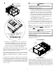
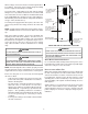
WARNING LIFT OVER APPROXIMATE CENTER OF UNIT TO PREVENT POSSIBLE EQUIPMENT DAMAGE, PROPERTY DAMAGE, PERSONAL INJURY OR DEATH, THE FOLLOWING BULLET POINTS MUST BE OBSERVED WHEN INSTALLING THE UNIT. SPREADER BARS MUST BE USED WITH LIFTING STRAPS THAT ARE LESS THAN 16 FEET LONG • Sufficient structural support must be determined prior to locating and mounting the curb and package unit. • Ductwork must be constructed using industry guidelines.
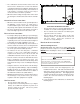
removal, to allow service access and to insure proper ventilation and condenser airflow. The unit must not be installed beneath any obstruction. The unit should be installed remote from all building exhausts to inhibit ingestion of exhaust air into the unit fresh air intake. RIGGING DETAILS WARNING TO PREVENT PROPERTY DAMAGE, THE UNIT SHOULD REMAIN IN AN UPRIGHT POSITION DURING ALL RIGGING AND MOVING OPERATIONS.
CAUTION TO PREVENT SEVERE DAMAGE TO THE BOTTOM OF THE UNIT, DO NOT FORK LIFT UNIT AFTER WOOD STRUTS HAVE BEEN REMOVED. Bring condenser end of unit into alignment with the curb. With condenser end of the unit resting on curb member and using curb as a fulcrum, lower opposite end of the unit until entire unit is seated on the curb. When a rectangular cantilever curb is used, care should be taken to center the unit. Check for proper alignment and orientation of supply and return openings with duct.
All line voltage connections must be made through weatherproof fittings. All exterior power supply and ground wiring must be in approved weatherproof conduit. Line voltage connects to middle contactor on 460v and 575v Gas Packs The main power supply wiring to the unit and low voltage wiring to accessory controls must be done in accordance with these instructions, the latest edition of the National Electrical Code (ANSI/NFPA 70), and all local codes and ordinances.
GAS SUPPLY PIPING WARNING TO PREVENT PERSONAL INJURY OR DEATH DUE TO IMPROPER INSTALLATION, ADJUSTMENT, ALTERATION, SERVICE OR MAINTENANCE, REFER TO THIS MANUAL . FOR ADDITIONAL ASSISTANCE OR INFORMATION, CONSULT A QUALIFIED INSTALLER, SERVICE AGENCY OR THE GAS SUPPLIER. IMPORTANT NOTE: This unit is factory set to operate on natural gas at the altitudes shown on the rating plate.
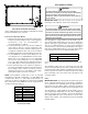
Natural Gas Connection GAS INLET LOCATION (3/4” NPT) Natural Gas Capacity of Pipe in Cubic Feet of Gas Per Hour (CFH) Nominal Black Pipe Size (inches) Length of Pipe in Feet 1 1/2 3/4 1 1/4 1 1/2 10 132 278 520 1050 1600 20 92 190 350 730 1100 30 73 152 285 590 980 40 63 130 245 500 760 50 56 115 215 440 670 60 50 105 195 400 610 70 46 96 180 370 560 80 43 90 170 350 530 90 40 84 160 320 490 100 38 79 150 305 460 Pressure = .50 PSIG or less and Pressure Drop of 0.3" W.C. (Based on 0.
1. Vaporization rate, which depends on (a) temperature of the liquid, and (b) wetted surface area of the container or containers. 2. Proper pressure regulation. 3. Pressure drop in lines between regulators, and between second stage regulator and the appliance. Pipe size required will depend on length of pipe run and total load of all appliances.
3. 4. 5. 6. NOTE: The gas connection size at the unit does NOT establish the size of the supply line. These units are designed for either natural or propane (LP) gas and are specifically constructed at the factory for only one of these fuels. The fuels are NOT interchangeable. However, the furnace can be converted in the field from natural gas to LP gas with the appropriate factory kit (see unit Technical Manual for the appropriate kit).
STARTUP, ADJUSTMENTS, AND CHECKS TOOLS REQUIRED Refrigeration gauge and manifold Voltmeter Clamp-on ammeter Ohmmeter Test lead (Minimum #16 AWG with insulated alligator clips) Manometer for verifying gas pressure 0 to 20" w.c.
System Voltage - That nominal voltage value assigned to a circuit or system for the purpose of designating its voltage class. SET EVAPORATOR FAN RPM Actual RPM’s must be set and verified with a tachometer or strobe light. Refer to Appendices A and B for basic unit fan RPM. Refer also to “Airflow” section of this manual. With disconnect switch open, disconnect thermostat wires from terminals Y and W. This will prevent heating and mechanical cooling from coming on.
Check tension frequently during the first 24 hours of operation. Subsequent retensioning should fall between the minimum and maximum force. To determine the deflection distance from the normal position, use a straightedge or stretch a cord from sheave to sheave to use as a reference line. On multiple belt drives, an adjacent undeflected belt can be used as a reference.
With Power And Gas On: Input = 1000 x 3600 / 34 = 106,000 BTU per Hour. NOTE: BTU content of the gas should be obtained from the gas supplier. This measured input must not be greater than shown on the unit rating plate. 4. Relight all other appliances turned off in step 1. Be sure all pilot burners are operating. 2. Put unit into heating cycle and turn on all other gas consuming appliances. INLET GAS PRESSURE NATURAL Min. 5.0" W.C., Max. 10.0" W.C. PROPANE Min. 11.0" W.C., Max. 14.0" W.C.
4. The belt drive blower contactor closes its contacts L1, L2 and L3 to T1, T2 and T3 to provide power to the supply fan motor. 5. Check supply fan rotation. If the supply fan is rotating in the wrong direction, disconnect and lock off Single Point Power Block. Do not attempt to change load side wiring. Internal wiring is set at the factory to assure that the supply fan and compressors all rotate in the proper direction.
The pressure regulator on LP gas models is adjusted for 10.0" w.c. manifold pressure and is intended to prevent over-firing only. Do not attempt adjustment of the built-in pressure regulator unless the supply pressure is at least 7.0" w.c. on natural gas or 14.0" w.c. on propane gas. Check the location of the ignition electrode and the flame sensor for correct gap setting. NORMAL SEQUENCE OF OPERATION HEATING This unit has one (RS) Manual Reset Limit Control Switch.
The diagnostic fault code is 1 flash for a lockout due to failed ignition attempts or flame dropouts. The integrated control will automatically reset after one hour, or it can be reset by removing the thermostat signal or disconnecting the electrical power supply for over five seconds.
Open Thermal Protection Device the range specified on the unit data plate. NOTE: Thermal efficiency of the furnace is a product efficiency rating determined under continuous operating conditions independent of any installed system. If the primary limit switch opens, the gas valve is immediately deenergized, the induced draft and air circulating blowers are energized. The induced draft and air circulator blowers remain energized until the limit switch recloses.
for the purpose of airflow balancing, but once the balance has been achieved, fixed sheaves maintain alignment and minimize vibration more effectively. For direct drive units, move green wire for fan. WARNING TO PREVENT PERSONAL INJURY OR DEATH DUE TO IMPROPER INSTALLATION, ADJUSTMENT, ALTERATION, SERVICE OR MAINTENANCE, REFER TO THIS MANUAL . FOR ADDITIONAL ASSISTANCE OR INFORMATION, CONSULT A QUALIFIED INSTALLER, SERVICE AGENCY OR THE GAS SUPPLIER.
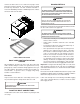
Disposable return air filters are supplied with this unit. See the unit Specification Sheet or Technical Manual for the correct size and part number. To remove the filters, remove the filter access panel on return side of the unit. d. The entire burner assembly can now be removed from the unit. NOTE: Use all screws that were removed; they are necessary for safe and proper operation of the unit. 3. Inspect and periodically clean the vent outlet (bird screen) on the access panel.
APPENDIX A BLOWER PERFORMANCE DATA BELT DRIVE - STANDARD HORIZONTAL CPG180 STANDARD BELT DRIVE TURNS OPEN ESP, In H2 O 0 1 2 3 4 5 6 CFM BHP CFM BHP CFM BHP CFM BHP CFM BHP CFM BHP CFM BHP 0.2 --- --- --- --- --- --- --- 0.00 6827 2.67 6394 2.28 5982 1.94 0.4 --- --- --- --- 7079 3.20 6623 2.76 6161 2.34 5706 1.98 5271 1.66 0.6 --- --- 6903 3.32 6405 2.83 5923 2.41 5434 2.02 4949 1.68 --- --- 0.8 6717 3.42 6198 2.92 5668 2.45 5152 2.
APPENDIX A BLOWER PERFORMANCE DATA BELT DRIVE - HIGH STATIC CPG180 HIGH STATIC BELT DRIVE TURNS OPEN ESP, In H2 O 0 1 2 3 4 5 6 CFM BHP CFM BHP CFM BHP CFM BHP CFM BHP CFM BHP CFM BHP 1.0 --- --- --- --- --- --- --- --- 6690 3.69 6008 3.02 5321 2.43 1.2 --- --- --- --- --- --- 6653 3.95 5922 3.22 5182 2.58 --- --- 1.4 --- --- --- --- 6634 2.80 5857 3.44 5056 2.74 --- --- --- --- 1.6 --- --- 6638 4.55 5808 2.43 4948 2.
APPENDIX B ELECTRICAL DATA ELECTRICAL DATA MODELS 15 TON VOLTAGE (NAMEPLATE) VOLTAGE LIMITATIONS LARGER COMPRESSOR SMALLER COMPRESSOR OD FAN MOTORS (ea) ID FAN MOTOR ID MOTOR APPL MIN MAX Qty RLA LRA Qty RLA LRA Qty HP RLA HP FLA 208/230-60-3 187 253 1 29.5 195.0 1 25.0 164.0 3 1/3 2.40 BD STD STATIC 5.0 12.7 460-60-3 414 506 1 14.7 95.0 1 12.2 100.0 3 1/3 1.20 BD STD STATIC 5.0 6.4 575-60-3 518 633 1 12.2 80.0 1 9.0 78.0 3 1/3 0.
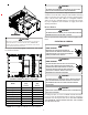
APPENDIX C UNIT DIMENSIONS Model A B C D 15 Ton 20 Ton 133-1/2" 88-7/32" 50-9/32" 5-5/32" B A C D 21” 60” 7” 48” 22” VERTICAL DISCHARGE (TOP VIEW) 27
CPG1803503B* & CPG2404003B* THREE PHASE 208-230/60 HZ BELT DRIVE WIRING DIAGRAM BK OR OR RD BK RD BK RD OR RD OR RD BK OR OR WH OR BK L1 L2 L3 L1 OR L2 L3 L1 CC 2 BC T1 T1 T3 T2 PB RD BK T2 L2 L3 T2 T3 POWER SUPPLY 208V / 240V - 3 ph - 60 Hz SEE NOTE 4 BK CC 1 T3 BL T1 BL GR BK RD RD BL OR RD BL BK C PU FC1 BL BK OR BL YL RD BK YL YL YL RD BK F BR RD EM BL BL PU BK RD C FC2 CCH2 COMP 2 T1 BK T2 RD T3 YL F BR RD BL BK PU OR
CPG1803503B* & CPG2404003B* THREE PHASE 208-230/60 HZ BELT DRIVE WIRING DIAGRAM SUPPLY VOLTAGE 208-240/3/60 L1 T2 CC1 L3 L2 T2 T1 T1 C OMP1 T3 CC1 T3 C RCCF1 F CM1 HIGH VOLTAGE! DISCONNECT ALL POWER BEFORE SERVICING OR INSTALLING THIS UNIT. MULTIPLE POWER SOURCES MAY BE PRESENT. FAILURE TO DO SO MAY CAUSE PROPERTY DAMAGE, PERSONAL INJURY OR DEATH.
CPG1803504B*/7B & CPG2404004B*/7B* THREE PHASE 460-575/60 HZ BELT DRIVE WIRING DIAGRAM P OWER SUPPLY 460V / 575 - 3 ph - 60 Hz SEE NO TE 4 BL OR BL RD OR OR RD RD BK RD BK L1 L2 WH BK BK BK BL BL L3 L1 GRND L2 L 2 L 3 L3 L1 CC 2 BC T1 T3 T2 T1 T2 T 2 L2 L3 T2 T3 CC 1 T3 T1 BL BL HIGH VOLTAGE! DISCONNECT ALL POWER BEFORE SERVICING OR INSTALLING THIS UNIT. MULTIPLE POWER SOURCES MAY BE PRESENT. FAILURE TO DO SO MAY CAUSE PROPERTY DAMAGE, PERSONAL INJURY OR DEATH.
CPG1803504B*/7B & CPG2404004B*/7B* THREE PHASE 460-575/60 HZ BELT DRIVE WIRING DIAGRAM SUPPLY VOLTAGE 460-575/3/60 L1 T2 CC1 L2 L3 CC1 T1 COMP1 T3 CC1 T3 C RCCF1 F CM1 C HIGH VOLTAGE! DISCONNECT ALL POWER BEFORE SERVICING OR INSTALLING THIS UNIT. MULTIPLE POWER SOURCES MAY BE PRESENT. FAILURE TO DO SO MAY CAUSE PROPERTY DAMAGE, PERSONAL INJURY OR DEATH.
© 2010 Goodman Manufacturing Company, L.P. 5151 San Felipe, Suite 500 ◊ Houston, TX 77056 www.goodmanmfg.com www.amana-hac.