These furnaces comply with requirements embodied in the American National Standard / National Standard of Canada ANSI Z21.47·CSA-2.3 Gas Fired Central Furnaces. ® US C INSTALLATION & OPERATING INSTRUCTIONS for AMV8 GAS FIRED WARM AIR FURNACE 2-STAGE (CATEGORY 1) RECOGNIZE THIS SYMBOL AS A SAFETY PRECAUTION. ATTENTION INSTALLING PERSONNEL As a professional installer you have an obligation to know the product better than the customer. This includes all safety precautions and related items.
Table of Contents I. Warnings .......................................................................................................................................................................... 3 TO THE OWNER ................................................................................................................................................ 4 TO THE INSTALLER ...................................................................................................................................
Table of Contents NORMAL COOLING SEQUENCE ........................................................................................................................... 21 CONSTANT FAN ............................................................................................................................................... 22 XII. Start-up Procedure and Adjustment .........................................................................................................................
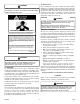
TO THE INSTALLER WARNING Before installing this unit, please read this manual thoroughly to familiarize yourself with specific items which must be adhered to, including but not limited to: unit maximum external static pressure, gas pressures, BTU input rating, proper electrical connections, circulating air temperature rise, minimum or maximum CFM, and motor speed connections, and venting. These furnaces are designed for Category I venting only.
3. Service integrated control module or connecting wiring following the discharge process in step 2. Use caution not to recharge your body with static electricity; (i.e., do not move or shuffle your feet, do not touch ungrounded objects, etc.). If you come in contact with an ungrounded object, repeat step 2 before touching control or wires. 4. Discharge your body to ground before removing a new control from its container. Follow steps 1 through 3 if installing the control on a furnace.
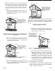
National Fire Protection Association 1 Batterymarch Park Quincy, MA 02269 • Provisions must be made for venting combustion products outdoors through a proper venting system. The length of flue pipe could be a limiting factor in locating the furnace. • Ensure adequate combustion air is available for the furnace. Improper or insufficient combustion air can expose building occupants to gas combustion products that could include carbon monoxide. Refer to Section V, Combustion and Ventilation Air Requirements.
Section 1.23.1. The following steps shall be followed with each appliance connected to the venting system placed in operation, while any other appliances connected to the venting system are not in operation: ACCESSIBILITY CLEARANCE,WHERE GREATER, SHOULD TAKE PRECEDENCE OVER MINIMUM FIRE PROTECTION CLEARANCE.
Consult the instructions packaged with the thermostat for mounting instructions and further precautions. safety exhaust, odor control, and air for compressors. (d) In addition to air needed for combustion, air shall be supplied for ventilation, including all air required for comfort and proper working conditions for personnel. V.
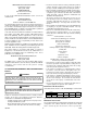
(b) All Air from Outdoors: The confined space shall be provided with two permanent openings, one commencing within 12 inches of the top and one commencing within 12 inches of the bottom of the enclosure. The openings shall communicate directly, or by ducts, with the outdoors or spaces (crawl or attic) that freely communicate with the outdoors. Chimney or Gas Vent 1.
5.3.5 Louvers and Grilles: In calculating free area in 5.3.3, consideration shall be given to the blocking effect of louvers, grilles or screens protecting openings. Screens used shall not be smaller than 1/4 inch mesh. If the area through a design of louver or grille is known, it should be used in calculating the size of opening required to provide the free area specified.
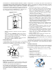
This inspection is based upon a draft topical report, “Masonry Chimney Inspection and Relining”, issued by the Gas Research Institute. While not yet finalized, we believe this report represents the best information on this subject which is currently available. VII. EXTERIOR MASONRY CHIMNEYS CATEGORY I FURNACES ONLY An exterior masonry chimney is defined as a “Masonry chimney exposed to the outdoors on one or more sides below the roof line.
CHECK 3 - CHIMNEY CROWN CONDITION. Damage from condensate usually shows up first in the crown. If any of the following trouble signs are present, the condition of the crown is not satisfactory: a) b) c) d) e) f) Crown leaning Bricks missing Mortar missing Tile liner cracked No tile liner Salt staining at mortar joints. (White stains, and mortar becomes sandy and/or erodes.) For problems a, b, or c, see Fix 3. If problems d, e, or f are present, see Fix 4.
If a metal liner is not present, a clay tile liner must be present, or the chimney must be lined (Fix 4). In some cases, a shorter extension above the roof may be possible with a liner than would be required with a masonry chimney. Use a flashlight and small mirror at the cleanout or vent connector to inspect the clay tile liner. If any of the following problems are present: For further information on relining, see Fix 4.
include indoor swimming pools and chlorine bleaches, paint strippers, adhesives, paints, varnishes, sealers, waxes (which are not yet dried) and solvents used during construction and remodeling. Various commercial and industrial processes may also be sources of chlorine/ fluorine compounds. WARNING TO AVOID THE RISK OF INJURY, ELECTRICAL SHOCK OR DEATH, THE FURNACE MUST BE ELECTRICALLY GROUNDED IN ACCORDANCE WITH LOCAL CODES OR, IN THEIR ABSENCE, WITH THE LATEST EDITION OF THE NATIONAL ELECTRIC CODE.
burner compartment will need to move the juction box directly over. 4. Attach the junction box to the right side of the furnace, using the screws removed in step 2. 5. Check the location wiring. Confirm that it will not be damaged by heat from the burners or by the rotation of the fan. Also confirm that wiring location will not interfere with filter removal or other maintenance. Low voltage connections can be made through either the right or left side panel.
3. Secure the dehumidistat hot wire (typically the black lead) to the screw terminal marked “R” on the furnace integrated control module. 4. Secure the dehumidistat ground wire (typically the green lead) to the ground screw on the furnace junction box. NOTE: Ground wire may not be present on all dehumidistats. 5. Turn ON power to furnace.
All field wiring must conform to applicable codes. Connections should be made as shown in the following illustration. NOTE: Adjusting the minimum supply pressure below the limits in the above table could lead to unreliable ignition. Gas input to the burners must not exceed the rated input shown on the rating plate. Overfiring of the furnace can result in premature heat exchanger failure. Gas pressures in excess of 13 inches water column can also cause permanent damage to the gas valve.
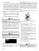
1,000 Btu/ft3 is determined by- WARNING Corrected Input = 90,000 - (6,000 X .04) X (90,000 / 1,000) Corrected Input = 90,000 - (240 X 90) POSSIBLE PROPERTY DAMAGE, PERSONAL INJURY OR DEATH MAY OCCUR IF THE CORRECT CONVERSION KITS ARE NOT INSTALLED. THE APPROPRIATE KITS MUST BE APPLIED TO INSURE SAFE AND PROPER FURNACE OPERATION. ALL Corrected Input = 90,000 - 21,600 Corrected Input = 68,400 Using the orifices sized as shown in the table for 6,000 feet (#45), a meter time of 52.6 seconds is measured.
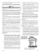
• Install a drip leg to trap dirt and moisture before it can enter the gas valve. The drip leg must be a minimum of three inches long. • Install a 1/8" NPT pipe plug fitting, accessible for test gage connection, immediately upstream of the gas supply connection to the furnace. • Use two pipe wrenches when making connection to the gas valve to keep it from turning. The orientation of the gas valve on the manifold must be maintained as shipped from the factory.
For satisfactory operation, propane gas pressure must be 11 inch WC at the furnace manifold with all gas appliances in operation. Maintaining proper gas pressure depends on three main factors: Sizing Between Single or Second Stage Regulator and Appliance* Maximum Propane Capacities Listed are Based on 1/2" W.C. pressure drop at 11" W.C. setting. Capacities in 1,000 BTU/hour. Pipe or Nominal Pipe Size Tubing Tubing Size, O.D.
• Integrated control module flashes LED lights. • Integrated control module monitors safety circuits continuously. • Furnace awaits call from thermostat. FILTERS - READ THIS SECTION BEFORE INSTALLING THE RETURN AIR DUCTWORK Filters must be used with this furnace. Discuss filter maintenance with the building owner. Filters do not ship with this furnace, but must be provided by the installer. Filters must comply with UL900 or CAN/ULCS111 standards.
1. Close the manual gas shutoff valve external to the furnace. 2. Turn off the electrical power to the furnace. 3. Set the room thermostat to the lowest possible setting. 4. Remove the burner compartment door. NOTE: This furnace is equipped with an ignition device which automatically lights the burner. Do not try to light the burner by hand. 5. Move the furnace gas valve manual control to the OFF position. 6. Wait five minutes then smell for gas.
gas piping drip leg. The supply pressure must be measured with manifold pressure, use the following procedure. the burners operating. To measure the gas supply pressure, use 1. Turn OFF gas to furnace at the manual gas shutoff valve the following procedure. external to the furnace. 2. Connect a calibrated water manometer (or appropriate gas With Power and Gas Off: pressure gauge) at the gas valve outlet pressure tap (refer 1.
blinks once for each 100 CFM of airflow. 5. Turn ON gas and relight appliances turned off in step 1. Ensure all the appliances are functioning properly and that all pilot burners are operating. 1. Determine the tonnage of the cooling system installed with the furnace. If the cooling capacity is in BTU/hr divide it by 12,000 to convert capacity to TONs. Example: Cooling Capacity of 30,000 BTU/hr. 30,000/12,000 = 2.5 Tons 2. Determine the proper air flow for the cooling system.
8 7 100% CFM 100% CFM 50% CFM OFF 8 7 ½ min Cooling Speed Tap B 1 m in 8 7 82% CFM 100% CFM Cooling Speed Tap D OFF 82% CFM 100% CFM O O F N F 4 3 2 1 * 8 7 6 5 Ramping* Profile Tap A Ramping Profile Tap B 8 7 6 5 8 7 6 5 8 7 6 5 O F F O F F O F F 7 4 3 2 1 O O F N F 8 7 4 3 2 1 O O N F F 8 7 4 3 2 1 * O O N N Cooling Speed Taps Heating Speed Taps ( * indicates factory setting) ON ON 3 2 1 Heat Off Delay 90 Seconds 4 3 2 1 ON OFF 3 2 1 Heat Off Delay 120 Seco
XIII. OPERATIONAL CHECKS WARNING WARNING TO PREVENT PREMATURE FAILURE OF HEAT EXCHANGER, PROPERTY DAMAGE, PERSONAL INJURY OR DEATH, DO NOT ADJUST THE LIMIT CONTROL (FACTORY TO AVOID PERSONAL INJURY OR DEATH, DO NOT REMOVE ANY INTERNAL COMPARTMENT COVERS OR ATTEMPT ANY ADJUSTMENT. ELECTRICAL COMPONENTS ARE CONTAINED IN BOTH COMPARTMENTS. TO PREVENT SET). XIII.
XV. TROUBLESHOOTING WARNING ELECTROSTATIC DISCHARGE (ESD) PRECAUTIONS NOTE: Discharge body’s static electricity before touching unit. An electrostatic discharge can adversely affect electrical components. TO AVOID ELECTRICAL SHOCK, INJURY OR DEATH, DISCONNECT ELECTRICAL 2. Firmly touch a clean, unpainted, metal surface of the furnace away from the control. Any tools held in a person’s hand during grounding will be discharged. 3.
UPRIGHT FILTER REMOVAL BURNERS To remove filters from an external filter rack in an upright upflow installation, follow the directions provided with external filter rack kit. Clean, wash and dry a permanent filter. When using a metal filter, both sides should be sprayed with a dust adhesive as recommended on adhesive container. Spray adhesives for use with permanent metal filters can be found at some hardware stores. BE SURE AIRFLOW DIRECTION ARROW POINTS TOWARDS THE BLOWER. Inspect filter.
Troubleshooting Chart Symptoms of Abnormal Operation Associated • Furnace fails to operate. NONE Fault Description(s) Possible Causes Corrective Action Cautions and Notes LED Code2 • Integrated control module diagnostic LED provides no signal. • No 115 volt power to furnace, or no 24 volt power to integrated control module. • Blown fuse or circuit breaker.
Troubleshooting Chart Symptoms of Abnormal Operation • Circulator blower runs continuously. No furnace operation. • Integrated control module diagnostic LED is flashing FOUR (4) flashes. Associated Fault Description(s) Possible Causes Corrective Action 4 • Primary limit circuit is open. • Insufficient conditioned air over the heat exchanger. Blocked filters, restrictive ductwork, improper circulator blower speed, or failed circulator blower. • Check filters and ductwork for blockage.
Wiring Diagram Ø /60 HZ POW ER SUPP LY WIT H TO 11 5VAC / 1 OV ERC URRE NT PRO TECT ION DE VICE WH 16 WI RE HA RNE SS L WAR NING : 24 V AC. H UM. 2 4 V T H E R MO S T A T CONNECTIONS TWIN/ DEHUM W2 W1 R G B/C Y YLO O FUSE 16 P IN PL UG RD 10 11 12 7 8 9 4 5 6 1 2 3 GND N DIS CONN ECT POWER BEF ORE SERV ICING . WIR ING TO U NIT MUS T BE PRO PERLY POL ARIZ ED A ND GRO UNDE D.
NOTE: SPECIFICATIONS AND PERFORMANCE DATA LISTED HEREIN ARE SUBJECT TO CHANGE WITHOUT NOTICE Quality Makes the Difference! All of our systems are designed and manufactured with the same high quality standards regardless of size or efficiency. We have designed these units to significantly reduce the most frequent causes of product failure. They are simple to service and forgiving to operate. We use quality materials and components. Finally, every unit is run tested before it leaves the factory.