INSTALLATION & OPERATING INSTRUCTIONS for A/GPG13 M SERIES W/R410A SINGLE PACKAGE GAS-ELECTRIC HEATING & COOLING UNIT Affix this manual and Users Information Manual adjacent to the unit. ® C US This Forced Air Central Unit Design Complies With Requirements Embodied in The American National Standard / National Standard of Canada Shown Below. ANSI Z21.47•CSA-2.3 Central Furnaces RECOGNIZE THIS SYMBOL AS A SAFETY PRECAUTION.
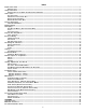
Index Replacement Parts ...................................................................................................................................................................... 3 ORDERING PARTS ....................................................................................................................................................................... 3 Safety Instructions ..................................................................................................................
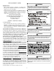
REPLACEMENT PARTS WARNING ORDERING PARTS DO NOT CONNECT TO OR USE ANY DEVICE THAT IS NOT DESIGN CERTIFIED When reporting shortages or damages, or ordering repair parts, give the complete unit model and serial numbers as stamped on the unit’s nameplate. BY GOODMAN FOR USE WITH THIS UNIT. SERIOUS PROPERTY DAMAGE, PERSONAL INJURY, REDUCED UNIT PERFORMANCE AND/OR HAZARDOUS CONDITIONS MAY RESULT FROM THE USE OF SUCH NON-APPROVED DEVICES.
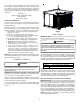
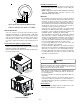
UNIT LOCATION WARNING TO PREVENT POSSIBLE EQUIPMENT DAMAGE, PROPERTY DAMAGE, PERSONAL INJURY OR DEATH, THE FOLLOWING BULLET POINTS MUST BE OBSERVED WHEN INSTALLING THE UNIT. ALL INSTALLATIONS: • • WARNING • TO PREVENT THE RISK OF PROPERTY DAMAGE, PERSONAL INJURY, OR DEATH, DO NOT STORE COMBUSTIBLE MATERIALS OR USE GASOLINE OR OTHER FLAMMABLE LIQUIDS OR VAPORS IN THE VICINITY OF THIS APPLIANCE.
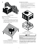
ROOF CURB INSTALLATIONS ONLY: • • • Sufficient structural support must be determined prior to locating and mounting the curb and package unit. Ductwork must be constructed using industry guidelines. The duct work must be placed into the roof curb before mounting the package unit. Curb insulation, cant strips, flashing and general roofing material are furnished by the contractor.
The heating and cooling capacities of the unit should be greater than or equal to the design heating and cooling loads of the area to be conditioned. The loads should be calculated by an approved method or in accordance with A.S.H.R.A.E. Guide or Manual J Load Calculations published by the Air Conditioning Contractors of America. Obtain from: American National Standards Institute 1430 Broadway New York, NY 10018 TRANSPORTATION DAMAGE Check the carton upon arrival for external damage.
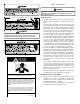
PIPING IMPORTANT NOTE: To avoid possible unsatisfactory operation or equipment damage due to under firing of equipment, do not undersize the natural/propane gas piping from the meter/tank to the unit. When sizing a trunk line, include all appliances on that line that could be operated simultaneously. The rating plate is stamped with the model number, type of gas and gas input rating. Make sure the unit is equipped to operate on the type of gas available.
PROPANE GAS INSTALLATIONS Sizing Between First and Second Stage Regulator Maximum Propane Capacities listed are based on 1 PSIG Pressure Drop at 10 PSIG Setting. Capacities in 1,000 BTU/HR PIPE OR TUBING LENGTH, FEET WARNING TO AVOID PROPERTY DAMAGE, PERSONAL INJURY OR DEATH DUE TO FIRE OR EXPLOSION CAUSED BY A PROPANE GAS LEAK, INSTALL A GAS DETECTING WARNING DEVICE.
Movement of air must not be obstructed by furniture, door, draperies, etc. The thermostat must not be mounted where it will be affected by drafts, hot or cold water pipes or air ducts in walls, radiant heat from fireplace, lamps, the sun, television, etc. Consult the Instruction Sheet packaged with thermostat for mounting instructions. All units have one stage of heating and one stage of mechanical cooling. Units which will have economizers may use thermostats with one or two stages of cooling.
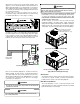
Down Discharge Applications Cut insulation around bottom openings and remove panels from the bottom of the unit, saving the screws holding the panels in place. NOTE: Single phase models require installation of horizontal duct kit #20464501PDGK (medium chassis) and #20464502PDGK (large chassis). G Y R W DUCTWORK From Unit Duct systems and register sizes must be properly designed for the C.F.M. and external static pressure rating of the unit.
VENTING 2. The spark igniter and gas valve energizes for 7 seconds. NOTE: The igniter produces a very intense electrical spark that ignites the gas. 3. The 30-second HEAT FAN ON delay time begins. 4. The unit delivers heat to the conditioned space until the thermostat is satisfied. 5. The gas valve deenergizes. The induced draft blower continues operation for a 29-second post-purge. 6. Ignition control begins timing the HEAT FAN OFF delay.
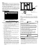
8. Smell for gas, including near the ground. This is important because some types of gas are heavier than air. If you have waited five minutes and you do smell gas, immediately follow the warnings on page 3 of this manual. If having waited for five minutes and no gas smell is noted, move the gas control valve switch to the ON position. 9. Replace the heat exchanger door on the side of the unit. 10. Open the manual gas valve external to the unit. 11. Turn on the electrical power supply to the unit. 12.
The line pressure supplied to the gas valve must be within the range specified in the chart on the next page. The supply pressure can be measured at the gas valve inlet pressure tap or at a hose fitting installed in the gas piping drip leg. The supply pressure must be measured with the unit OFF. To measure inlet pressure, use the following procedure. Gas Valve On/Off Selector Switch 8. Measure the gas supply pressure with burners firing.
6. Turn ON power and close thermostat “R” and “W” contacts to provide a call for heat. 7. Using a leak detection solution or soap suds, check for leaks at outlet pressure boss plug (Honeywell valve) or screw (White-Rodgers valve). Bubbles forming indicate a leak. SHUT OFF GAS AND REPAIR ALL LEAKS IMMEDIATELY! 8. Measure the gas manifold pressure with burners firing. Adjust manifold pressure using the Manifold Gas Pressure table shown below.
Adjust the thermostat setting below room temperature. 1. Main burners must go OFF. 2. Circulating Air Blower will continue to run for 120, 135 or 150 seconds, depending on the setting. 1 10 To ensure the unit is properly charged for the intended application, check the unit refrigerant superheat at the compressor. The refrigerant superheat is a function of outdoor ambient temperature and return air temperature of the conditioned space.
The diagnostic fault code is 1 flash for a lockout due to failed ignition attempts or flame dropouts. The integrated control will automatically reset after one hour, or it can be reset by removing the thermostat signal or disconnecting the electrical power supply for over five seconds.
5. When all heat exchanger tubes have been cleaned, replace the parts in the reverse order in which they were removed. 6. To reduce the chances of repeated fouling of the heat exchanger, perform the steps listed in “Startup, Adjustments, and Checks”. CABINET FINISH MAINTENANCE Use a fine grade automotive wax on the cabinet finish to maintain the finish’s original high luster. This is especially important in installations with extended periods of direct sunlight.
5. Replace burners and manifold, inspect the burner assembly for proper seating of burners in retention slots. 6. Reconnect electrical power and gas supply.
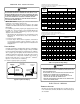
BLOWER PERFORMANCE DATA - SINGLE PHASE *PG1324045M41A* - Rise Range: 30° - 60° Unit Static 0.1 0.2 0.3 0.4 0.5 0.6 0.7 0.8 CFM 600 570 510 450 380 ---------------------- LOW WATTS AMPS 150 0.67 140 0.65 130 0.63 125 0.61 120 0.58 ------------------------------------------- CFM 1,190 1,140 1,080 1,025 975 920 830 730 HIGH WATTS AMPS 380 1.67 360 1.62 350 1.58 340 1.54 330 1.38 310 1.37 300 1.35 290 1.32 RISE NR NR 32 33 35 37 41 47 CFM 600 570 510 450 380 ---------------------- LOW WATTS AMPS 150 0.
BLOWER PERFORMANCE DATA - SINGLE PHASE *PG1336045M41A* - Rise Range: 30 -60° Unit Static 0.1 0.2 0.3 0.4 0.5 0.6 0.7 0.8 CFM 1,029 982 946 888 823 750 668 454 LOW WATTS AMPS 346 1.51 334 1.46 329 1.40 313 1.38 304 1.29 287 1.23 271 1.16 1.00 238 CFM 1,029 982 946 888 823 750 668 454 LOW WATTS AMPS 346 1.51 334 1.46 329 1.40 313 1.38 304 1.29 287 1.23 271 1.16 238 1.00 CFM 1,029 982 946 888 823 750 668 454 LOW WATTS AMPS 346 1.51 334 1.46 329 1.40 313 1.38 304 1.29 287 1.23 271 1.16 1.
BLOWER PERFORMANCE DATA - SINGLE PHASE *PG1348070M41A* - Rise Range: 35° - 65° Unit Static 0.1 0.2 0.3 0.4 0.5 0.6 0.7 0.8 CFM ------ -914 822 733 664 606 584 551 Unit Static 0.1 0.2 0.3 0.4 0.5 0.6 0.7 0.8 T4 COOLING SPEED CFM WATTS AMPS ------ ---------------1,593 449 3.55 1,545 463 3.69 1,506 476 3.82 1,448 481 3.87 1,400 493 3.95 1,341 502 4.00 1289 511 4.11 T1 HEATING SPEED WATTS AMPS --------------125 1.07 134 1.14 140 1.20 150 1.26 154 1.28 162 1.32 164 1.
BLOWER PERFORMANCE DATA - SINGLE PHASE *PG136090M41A* - Rise Range: 45° - 75° Unit Static 0.1 0.2 0.3 0.4 0.5 0.6 0.7 0.8 CFM 1,125 1,049 1,000 910 857 809 739 703 Unit Static 0.1 0.2 0.3 0.4 0.5 0.6 0.7 0.8 T4 COOLING SPEED CFM WATTS AMPS 1,942 649 4.83 1,883 657 4.87 1,859 670 4.96 1,827 675 4.97 1,749 683 4.99 1,706 693 5.10 1,655 703 5.12 1,588 705 5.11 T1 HEATING SPEED WATTS AMPS 162 1.44 168 1.53 178 1.60 184 1.64 197 1.75 201 1.83 207 1.86 218 1.
BLOWER PERFORMANCE DATA - HEATING SPEEDS THREE PHASE GPG1336090M43A* - Rise Range: 45° - 75° Unit Static 0.1 0.2 0.3 0.4 0.5 0.6 0.7 0.8 Unit Static 0.1 0.2 0.3 0.4 0.5 0.6 0.7 0.8 Unit Static 0.1 0.2 0.3 0.4 0.5 0.6 0.7 0.8 Unit Static 0.1 0.2 0.3 0.4 0.5 0.6 0.7 0.8 CFM 1100 1037 991 926 831 773 669 - LOW WATTS AMPS 342 1.57 335 1.52 320 1.45 308 1.39 290 1.32 279 1.25 260 1.17 - RISE 47 49 52 55 59 63 73 - CFM 1655 1579 1483 1407 1329 1210 1036 - HIGH WATTS AMPS 604 2.67 587 2.68 567 2.62 547 2.
BLOWER PERFORMANCE DATA - COOLING SPEEDS THREE PHASE GPG1336***M43A* - COOLING SPEEDS Unit Static 0.1 0.2 0.3 0.4 0.5 0.6 0.7 0.8 CFM 1,655 1,579 1,483 1,407 1,329 1,210 1,036 - Unit Static 0.1 0.2 0.3 0.4 0.5 0.6 0.7 0.8 GPG1348***M43A* - Rise Range: 45° - 75° T4 COOLING SPEED T5 COOLING SPEED CFM WATTS AMPS CFM WATTS AMPS ------------------------------------------1,593 449 3.55 1,669 532 4.22 1,545 463 3.69 1,654 239 4.25 1,506 476 3.82 1,610 551 4.30 1,448 481 3.87 1,545 557 4.36 1,400 493 3.
IGNITION CONTROL DIAGNOSTIC INDICATOR CHART Light Signal Off 1 Flash 2 Flashes 3 Flashes 4 Flashes 5 Flashes 6 Flashes Refer to Abnormal Heating or Cooling Operation Sections of this Manual Internal Control Failure External Lockout Pressure Switch Stuck Open Pressure Switch Stuck Closed Thermal Protection Device Open Flame Detected with Gas Valve Closed Short Cycle Compressor Delay (Cooling Only) HEATING TIMING CHART 100 % Circulator Blower OFF Gas Valve ON OFF Igniter ON OFF Induced Draft Blower O
APPENDIX UNIT DIMENSIONS FLUE EXHAUST HOOD A FLUE EXHAUST B B HEAT EXCHANGE ACCESS PANEL POWER WIRE ENTRANCE CONTROL WIRE ENTRANCE EXHAUST FLUE HOOD BLOWER ACCESS PANEL 26
*PG13(24,30,36,42)1** WIRING DIAGRAM P HIGH VOLTAGE! DISCONNECT ALL POWER BEFORE SERVICING OR INSTALLING THIS UNIT. MULTIPLE POWER SOURCES MAY BE PRESENT. FAILURE TO DO SO MAY CAUSE PROPERTY DAMAGE, PERSONAL INJURY OR DEATH.
*PG13(24,30,36,42)1** WIRING DIAGRAM HIGH VOLTAGE! DISCONNECT ALL POWER BEFORE SERVICING OR INSTALLING THIS UNIT. MULTIPLE POWER SOURCES MAY BE PRESENT. FAILURE TO DO SO MAY CAUSE PROPERTY DAMAGE, PERSONAL INJURY OR DEATH.
*PG13(48,60)1** WIRING DIAGRAM HIGH VOLTAGE! DISCONNECT ALL POWER BEFORE SERVICING OR INSTALLING THIS UNIT. MULTIPLE POWER SOURCES MAY BE PRESENT. FAILURE TO DO SO MAY CAUSE PROPERTY DAMAGE, PERSONAL INJURY OR DEATH.
*PG13(48,60)1** WIRING DIAGRAM HIGH VOLTAGE! DISCONNECT ALL POWER BEFORE SERVICING OR INSTALLING THIS UNIT. MULTIPLE POWER SOURCES MAY BE PRESENT. FAILURE TO DO SO MAY CAUSE PROPERTY DAMAGE, PERSONAL INJURY OR DEATH.
GPG13(36)3** WIRING DIAGRAM HIGH VOLTAGE! DISCONNECT ALL POWER BEFORE SERVICING OR INSTALLING THIS UNIT. MULTIPLE POWER SOURCES MAY BE PRESENT. FAILURE TO DO SO MAY CAUSE PROPERTY DAMAGE, PERSONAL INJURY OR DEATH.
GPG13(36)3** WIRING DIAGRAM HIGH VOLTAGE! DISCONNECT ALL POWER BEFORE SERVICING OR INSTALLING THIS UNIT. MULTIPLE POWER SOURCES MAY BE PRESENT. FAILURE TO DO SO MAY CAUSE PROPERTY DAMAGE, PERSONAL INJURY OR DEATH.
GPG13(48,60)3** WIRING DIAGRAM HIGH VOLTAGE! DISCONNECT ALL POWER BEFORE SERVICING OR INSTALLING THIS UNIT. MULTIPLE POWER SOURCES MAY BE PRESENT. FAILURE TO DO SO MAY CAUSE PROPERTY DAMAGE, PERSONAL INJURY OR DEATH.
GPG13(48,60)3** WIRING DIAGRAM HIGH VOLTAGE! DISCONNECT ALL POWER BEFORE SERVICING OR INSTALLING THIS UNIT. MULTIPLE POWER SOURCES MAY BE PRESENT. FAILURE TO DO SO MAY CAUSE PROPERTY DAMAGE, PERSONAL INJURY OR DEATH.
MINIMUM CLEARANCES 48" MIN 12" MIN 3" MIN . 12" MIN 36" MIN (FOR SERVICE) NOTE: Roof overhang should be no more than 36". UNIT Min.
NOTE: SPECIFICATIONS AND PERFORMANCE DATA LISTED HEREIN ARE SUBJECT TO CHANGE WITHOUT NOTICE Quality Makes the Difference! All of our systems are designed and manufactured with the same high quality standards regardless of size or efficiency. We have designed these units to significantly reduce the most frequent causes of product failure. They are simple to service and forgiving to operate. We use quality materials and components. Finally, every unit is run tested before it leaves the factory.