Z-Wave® Window/ Door Detector User's Manual
Table of Contents Safety instructions ....................................................................... 4 Copyright....................................................................................... 4 Trademarks ................................................................................... 4 Introduction................................................................................... 5 Features.........................................................................................
Before attempting to connect, operate or adjust this product, please save and read the User's Manual completely. The style of the product shown in this User's Manual may be different from the actual unit due to various models.
Introduction This unit is designed to detect the open or close status of door or window. It is easy to install and fully compatible with ® ® Z-Wave technology. With the built-in Z-Wave module, user can monitor the door or window status anywhere, even they are away from home. Besides, it can communicate with ® other Z-Wave devices, as long as the controller has been ® certified by Z-Wave .
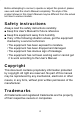
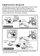
Application diagram The illustrations below show the applications of the Z-Wave ® Door/Window Detector. With the built-in Z-Wave , the ® detector can be remoted through a Z-Wave dongle or controller at home or anywhere. Note that the application may be different from the actual conditions.
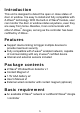
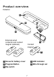
Product overview Detector 1 2 3 4 External wired contactor and contact magnet (optional) 5 Contact magnet 4 1 Screw for battery cover 3 Program Button 5 Dip switch 2 LED indicator 4 Wire through out 7
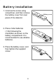
Battery installation 1. Unscrew the screw using screwdriver, and then remove the battery cover from rear panel of the detector. 2. Place 2 AAA batteries (1.5A) following the orientation as shown on the battery compartment. It is recommended to use alkaline batteries. 3. Place the battery cover, and then tighten the supplied screw.
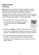
Operation Inclusion ® Note: Make sure a Z-Wave remote controller has been ® installed and included to an available Z-Wave network ® before joining the Z-Wave Window/Door Detector. ® Not all Z-Wave enabled remote controllers have the same installation process. Actual instructions may vary, it depends ® on the software that Z-Wave controller provided. 1. Before starting the inclusion process, be sure the DIP switch is setup to the default. To switch the DIP, refer to DIP switch chapter. Default setting 2.
Exclusion ® To exclude the Z-Wave network, operate the exclusion procedure from the controller, and then press ® button 3 times within 2 seconds on the Z-Wave Window/ Door Detector. Reset ® To reset the Z-Wave Window/Door Detector, press button 3 times within 2 seconds and the third for over 1 second.
Command classes Command class is a programming protocol which allows ® the Z-Wave Window/Door Detector to communicate with other compatible Z-Wave® devices. 2 association groups are ® supported by the Z-Wave Window/Door Detector. The Z-Wave® Window/Door Detector supports 2 association groups. Group1 supports the report of Alarm and warning message when the battery is low. Only one device can be associated in group1.
Z-Wave® Window/Door Detector Device Information Basic Type: BASIC_TYPE_ROUTING_SLAVE Generic Type: GENERIC_TYPE_SENSOR_BINARY Specific Type: SPECIFIC_TYPE_ROUTING_SENSOR_ BINARY Description of command class Sensor binary command class The user can also enquire the Sensor status of the unit SENSOR_BINARY_GET, it will return SENSOR_BINARY Command.
Battery Report Command: [Command Class Battery, Battery Report, Battery Level = 20%-100%] Wake up command class The Z-Wave® Window/Door Detector stays in sleep status for the majority of time in order to conserve battery power. However, it can be woken up at specified intervals by setting WAKE_UP_INTERVAL_SET command by Z-Wave® Controller.
Alarm command class The ALARM_REPORT will be sent to the controller when the batteries have been inserted properly into the Z-Wave® Window/Door Detector. 1. Power applied Once the batteries has been inserted, Alarm Report Command will be sent to Nodes in group1 to confirm the power status for the Z-Wave® Window/Door Detector. [Command Class Alarm , Alarm Report, Alarm Level = 0x02,Alarm Type = 0x01] 2.
Basic command class When door/window is opened, the will send Basic SET command contains a value that is adjustable, to the node of group2. For instance, a lamp module will be turned off after receiving the BASIC_SET command. Magnets to be opened: [Command Class Basic , Basic Set, Basic Value = 0xFF] Magnets to be closed: [Command Class Basic , Basic Set, Basic Value = 0x00] Configuration command class This class is used for setting certain vendor specific configuration variables to the node of group2.
Version command class Implemented according to command class specification. Manufacturer specific command class Implemented according to command class specification.
Association Within 30m approx. Define the relationship between devices after joining to Z-Wave® network. Device can be assigned as master/slave, and the slave can be controlled by the master. Within 30m approx. Within 30m approx.
® 1. Before associating the Z-Wave Window/Door Detector, please disconnect Detector and Contact Magnet. Wired contact Detector or Contact magnet Detector Contact magnet ® 2. Associate the Z-Wave Window/Door Detector with a controller. ® 3. Associate the appliances under Z-Wave Window/Door Detector using Z-Wave® controller or utility software. The supported appliances is up to 5. 4.
Dip switch ® The Z-Wave Window/Door detector can be setup to internal or external connections. Follow the steps below to adjust the dip before installing the detector to a door or window. 1. Loosen the screws from the rear panel, and then remove the cover. 2. Adjust the dip switches using a finger or finger nail according to the desired connection of the Window/Door detector.
Installation ® Before installing the Z-Wave Window/Door Detector, make sure the Detector has been included to a Z-Wave® network. Internal connection 1. Adjust the dip switch to the default. Refer to Dip switch chapter for more details. ® 2. Mount the Z-Wave Window/ Door detector to a window or door following the previous section. 3. Install the contact magnet to the moving part of the window or door opposite to the detector. Make sure the window or door is closed when installing.
Extension the detector (optional) Sometimes the type of window or door may differ from the previous section, users may need to extend the Window/ Door Detector using wires. 1. Adjust the dip switch according to the desired connection before installing to a door or window. Refer to Dip switch chapter for more details. 2. Extend the wired contact using two core (24AWG) wires and the maximum length is 4m. Refer to the Assemble the wire chapter for more information.
Assemble the wire 1. Loosen the screws from the rear panel, and then remove the cover. Detector Wired contactor 2. Insert the cable (24AWG) into the block as shown below, and then tighten the screws on the top.
Mounting the detector ® The Z-Wave Window/Door Detector can be mounted on any location that can be open or closed, such as closets, doors, windows or safes. 1. Unscrew the battery cover from the detector and slide the cover off. 2. Use the screws that are provided to screw the cover onto your desired location. Battery cover Battery cover 3. Slide the detector back on the cover.
4. Tighten the screw. 5. Install the contact magnet to the moving part of the window or door which is opposite to the detector using screws.
LED indicator Refer to the table below to see the status of LED. LED Description ® Green Flashes when including to a Z-Wave network ® Flashes when excluding from a Z-Wave network Flashes when data transmitting or receiving Lights green when waking up from sleeping mode * Sleeping mode: To save the power, the detector will enter sleeping mode automatically after 5 seconds when the installation is completed.
Specifications Item Protocol Detective type Power LED Indicator Switch Frequency Operating Rang Data Rate Application Working Environment Dimensions (LxWxH) Housing Flame Class Surface Processing Compliance Description ® Z-Wave Magnetism reed switch AAA battery 1.5V*2 Bicolor LED (Green / Red) Inclusion / Exclusion button 908.42MHz Up to 100 feet (30m) approx. 9.6kbps / 40kbps Indoor use Operating Temperature: 0~40ºC Storage Temperature: -10~55ºC Detector: 130x28x21.
Regulatory compliance FCC conditions This equipment has been tested and found to comply with the limits for a Class B digital device, pursuant to part 15 of the FCC rules. These limits are designed to provide reasonable protection against harmful interference in a residential installation. This equipment generates, uses and can radiate radio frequency energy and, if not installed and used in accordance with the instructions, may cause harmful interference to radio communications.