
Air Conditioner User Manual
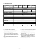
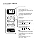
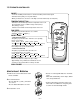
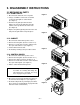
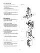
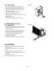
Table Of Contents

1.2 SPECIFICATIONS
• NOTE: Specifications are subject to minor change without notice for further improvement.
—3—
MODELS
ITEMS
COOLING CAPACITY (BTU/h) 5,300 5,200 5,200 6,000 6,000
POWER SUPPLY (Phase, V, Hz) 1ø, 115V, 60HZ
INPUT (W) 530 470 610 620
OPERATING CURRENT (AMP.) 4.8 4.3 5.6 5.8
REFRIGERANT CONTROL CAPILLARY TUBE
REFRIGERANT CHARGE (R-22) 230g (8.1 Oz ) 330g(11.6 Oz) 335g (11.8 Oz)
235g (8.3 Oz)
INSIDE FAN TURBO
OUTSIDE FAN PROPELLER FAN WITH SLINGER RING
AIR DISCHARGE 2-WAY (RIGHT AND LEFT)
CHASSIS TOP-DOWN
PROTECTOR
TEMPERATURE CONTROL THERMISTOR
ROTARY SWITCH
5 POSITIONS (LOW FAN, HIGH FAN, OFF, HIGH COOL, LOW COOL)
FAN MOTOR
6 POLES, 16W
6 POLES, 21.3W 6 POLES, 24W 6 POLES,
21.4W
• OVERLOAD PROTECTOR FOR COMPRESSOR
• INTERNAL PROTECTOR FOR FAN MOTOR
M5403R M5203R M5203L
M6003R
WM-6011
LWJ0611PCG
LWC061JGMK1
1.3 SAFETY PRECAUTIONS
1. When servicing, set the POWER of CONTROL
BOARD to Off and unplug the power cord.
2. Observe the original lead dress.
If a short circuit is found, replace all parts which
have been overheated or damaged by the short cir-
cuit.
3. After servicing, make an insulation resistance test
to prevent the customer's exposure to shock
hazards.
1.4
INSULATION RESISTANCE TEST
1. Unplug the power cord and connect a jumper
between 2 pins (black and white).
2. The grounding conductor (green or green and yel-
low) is to be open.
3. Measure the resistance value with an ohm meter
between the jumpered lead and each exposed
metallic part on the equipment at all Mode [except
POWER OFF].
4. The value should be over 1 MΩ.