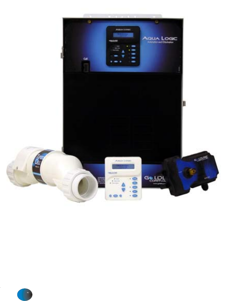
Aqua Logic Automation and Chlorination (actuators & remote display not included on some models - order separately) Operation Manual for models AQ-LOGIC-P-4 (all datecodes) AQ-LOGIC-PS-4 (0401 & earlier) G LDLINE CONTROLS INC. www.goldlinecontrols.
IMPORTANT SAFETY INSTRUCTIONS When using this electrical equipment, basic safety precautions should always be followed, including the following: • READ AND FOLLOW ALL INSTRUCTIONS • ! WARNING: Disconnect all AC power during installation. • ! WARNING: Water in excess of 100 degrees Fahrenheit may be hazardous to your health. • ! WARNING: To reduce the risk of injury, do not permit children to use this product unless they are closely supervised at all times.
Table of Contents System Overview Block Diagram....................................................................... Automation............................................................................. Chlorination............................................................................ Default Display...................................................................... 1 1 2 2 Manual System Operation Filter Pump.............................................................................
System Overview The Aqua Logic is a multifunction pool controller used to fully manage your pool/spa system. The Aqua Logic can control pumps, valves, lighting, heaters, and chlorination. Although the Aqua Logic is easy to use, it is important to completely read through this operating manual before attempting to operate the control.
Chlorination The Aqua Logic is also an automatic chlorine generation system for pool and/or spa sanitization. The operation requires a low concentration of salt (sodium chloride) in the pool/spa water. The Aqua Logic automatically converts the salt into free chlorine which kills bacteria and algae in the pool/spa. Chlorine will revert back to sodium chloride after killing bacteria. These reactions will continuously recycle virtually eliminating the need to add sanitizing chemicals to your pool/spa.
Manual System Operation While the main objective of the Aqua Logic is to automate the operation of your pool/spa system, there may be certain times when you want to override the automatic operation and control the equipment manually. To operate the pool equipment manually while keeping the automation active, perform the following procedures.
Pool/Spa Valves Pool-only or spa-only systems: The POOL/SPA button has no function. Pool and Spa systems without spa spillover: In pool-only mode (the left LED illuminated), press the POOL/SPA button to switch to spa-only operation (right LED illuminated). Pressing the POOL/SPA button again will switch back to pool-only. Pool and Spa systems with spa spillover: When currently in the pool-only mode (the left LED illuminated), press the POOL/SPA button to switch to spa-only operation (right LED illuminated).
Automatic System Operation The Aqua Logic controls most of your pool equipment automatically in order to minimize the time spent working on your pool. Most of the pool equipment can be programmed to operate on a timeclock basis. In addition, the desired pool and spa temperatures and pool and spa chlorinator settings can be programmed. This section will guide you on how to program the automatic operation for each function.
Programming Menu Flowchart The Aqua Logic’s five menus have many items in each menu that allow you to customize the operation of your pool/spa equipment. The chart below shows the Aqua Logic’s five menus as well as each menu’s specific settings. The Default Menu is a series of informative displays (temperatures, salt levels, chlorinator settings, etc.) with nothing to set.
The Settings Menu and the Timers Menu are the menus you will be using most often to adjust the operation of your pool. The Configuration Menu is used when the system is installed and defines what equipment is connected to each output and the operational logic that will control the equipment. This menu is normally “locked” and should only be used by a pool professional. Details regarding the Configuration menu are included in the Aqua Logic Installation Manual.
+ > Super Chlorinate On > Turn super chlorinate on or off Move to previous/next menu item When you have an unusually high bather load, a large amount of rain, a cloudy water condition, or any other condition that requires a large amount of chlorine to be introduced to the pool, activate the Aqua Logic Super-Chlorinate function. The Aqua Logic will turn on the filter pump, set the pool/spa valves to the correct position, and set the chlorine generator to maximum output.
+ > Display Light On for 60 sec. > Toggle between Always On and On for 60 sec. Move to previous/next menu item This function controls the blue backlight on the display. If the “60 seconds” option is selected, then the backlight will automatically turn off 60 seconds after the last key is pressed and will stay off until next time a key is pressed. Note that the Display Light selection only applies to the display keypad that you are currently using. Other display/keypads will not be affected.
The Countdown timer is programmed in increments of 5 minutes from “0:00” to a maximum of “21:00”. When “0:00” is programmed, the countdown timer is disabled and the output will be manually controlled. When a countdown timer is greater than “0:00”, pressing the appropriate output button will turn the output on and start the timer. When the programmed time has elapsed, the output will automatically turn off.
precedence over all other automatic functions, only manual operation of the filter button or pool/spa valve button will override this function. Refer to page 9 for general notes regarding timeclock programming. If your pool has a separate jet pump or blower controlled by Aux1 and/or Aux2 , you will have to program those separately (see below).
+ > Valve3-weekdays 8:30A to 4:00P + > Valve3-weekends 8:30A to 4:00P + > > Adjust time s setting Move between start and stop times & to previous/next menu item > Adjust time setting Move between start and stop times & to previous/next menu item > Adjust time setting Move between start and stop times & to previous/next menu item This menu will appear only if Valve3 is configured for timeclock. The valve will rotate on and off at the designated times. There is no manual override.
Configuration Menu Items Each item needs to be programmed and may contain additional sub-menu items. Refer to the following pages for information on programming. + > Freeze Protect Enabled + > Filter Pump 1 Speed + > Filter Config.
Heater Extend If “Enabled”, the filter extend logic keeps the filter pump running beyond the normal turn-off time if heat is still available. When heat is no longer available, both the valve/pump and filter pump will turn off simultaneously. Heater extend will NOT cause the filter pump to turn on, it will only delay the turn off time when the heater is operating.
if “Pool and Spa” is selected and if “Spa Spillover” is enabled Filter Operation Spa Spillover + + > Spa Spillover Disabled > if “Pool and Spa” is selected + > Pool/Spa Setup Pool and Spa + > Pool/Spa Setup + to view/change > Push to access Pool/Spa options Move to previous/next configuration menu item > Rotates between Pool and Spa, Spa Only, and Pool Only (default) options Move to next menu item > Toggle between Enabled and Disabled (default) Spa Spillover Move to next menu item > Tog
Note that Aux1 and Aux2 configuration are identical. Follow the steps below to program either output.
+ > Valve3 Function Solar + > Valve3 Config.
Initiate reset of all configuration parameters Move to previous/next configuration menu item (config not reset) + > Reset all configuration parameters Move to previous/next configuration menu item (config not reset) > Config.
Quick “How To” Guide Operate the Spa—manually 1. Press the “Pool/Spa” button to go to “spa-only” operation (right LED illuminated). In some cases, this may take more than one press of the button. 2. If the filter pump is not already on, press the “Filter” button to turn it on. 3. If the spa is below the desired temperature, the heater will turn on automatically when the filter pump is on and the valves are in the spa-only position.
3. Press the “+” or “-“ buttons repeatedly to adjust the setting. If you adjust the setting to 0% the chlorinator will be off all the time Note: Separate chlorinator output levels for the pool and spa must be set. If the valves are in the pool-only or spa spillover positions, then the chlorinator will operate per the pool setting. If the valves are in the spa-only position then the chlorinator will operate according to the spa setting.
Enter/Exit Service (or Service—Timed) mode 1. Go to Aqua Logic main unit (normally mounted near the pool equipment) 2. Pressing the “Service” button rotates through normal operation (red LED off), service mode (red LED on continuously) and service-timed mode (red LED flashing). Note: This operation can only be performed at the main Aqua Logic unit. Both “Service” and “Service-Timed” disable all automatic programmed operations and allow manual operation from the main unit only.
Chlorinator Operation / Pool Chemistry The table below summarizes the levels that are recommended by the National Spa and Pool Institute (NSPI). The only special requirements for the Aqua Logic are the salt level and stabilizer. It is important to maintain these levels in order to prevent corrosion or scaling and to ensure maximum enjoyment of the pool. Test your water periodically.
Salt Level Use the chart on page 18 to determine how much salt in pounds or (Kgs) need to be added to reach the recommended levels. Use the equations below (measurements are in feet/gallons and meters/liters) if pool size is unknown. Liters Gallons (pool size in meters) (pool size in feet) Rectangular Length x Width x Average Depth x 7.5 Length x Width x Average Depth x 1000 Round Diameter x Diameter x Average Depth x 5.
24 POUNDS and (Kg) OF SALT NEEDED FOR 3200 PPM Gallons and (Liters) of Pool/Spa water (76) 150 (68) 133 (61) 117 (53) 100 (45) 83 133 (61) 120 (55) 107 (48) 93 (42) 80 (36) 67 260 OK Dilute OK Dilute OK Dilute 3400 3600+ Ideal Ideal (9) 20 Dilute OK Ideal (11) 23 (21) (18) (32) 47 (27) 93 (42) (53) 117 (64) 140 (74) 163 (85) 187 (95) 210 (106) 40 60 80 (36) (45) 100 (55) 120 (64) 140 (73) 160 (82) 180 (91) 233 (117) 200 257 220 (100) 2
25 80 ppm 70 ppm 60 ppm 50 ppm 40 ppm 30 ppm 20 ppm 10 ppm 0 ppm (1.6) 1.7 (1.1) 0.8 (.54) (1.4) 1.3 (.91) 0.7 (.45) 0.0 2.5 0.0 (2.1) 2.0 3.3 2.7 (1.8) (2.7) (2.3) 0.0 (.45) 1.0 (.91) 2.0 (1.4) 3.0 (1.8) 4.0 (2.3) 5.0 3.3 4.2 (2.7) 6.0 7.0 (3.2) 8.0 (3.6) (2.7) 4.0 5.8 (3.7) 4.7 (3.2) 6.7 (4.3) (3.6) 5.3 8.0 0.0 (.54) 1.2 (1.1) 2.3 (1.6) 3.5 (2.1) 4.7 (2.7) 5.9 0.0 (.64) 1.4 (1.2) 2.7 (1.8) 4.0 (2.4) 5.4 (3.0) 6.7 (3.6) 7.
System Maintenance To maintain maximum performance, it is recommended that you open and visually inspect the cell every 3 months or after cleaning your filter. The Aqua Logic will remind you to do this by displaying the message “Inspect/Clean Cell” after approximately 500 hours of operation. The Aqua Logic electrolytic cell has a self cleaning feature incorporated into the electronic control’s logic. In most cases this self cleaning action will keep the cell working at optimum efficiency.
Troubleshooting and Diagnostic Information The Aqua Logic provides 2 different tools to aid in troubleshooting any problems that may occur in your pool and/or spa system. The Service mode will allow you to disable automatic operation and manually control most of the equipment (the heater and general purpose Valve3 output are the exceptions). The Diagnostic Menu will provide some detailed information regarding system operation.
Diagnostic Menu To enter the Diagnostic Menu, press the “Menu” button repeatedly until the display shows “Diagnostic Menu”. At this point, you can use either the “<” or “>” buttons to scroll through the various menu items which are described below: + > +23.45 Set Day and +6.75A Time Wednesday 84°F 3200PPM 10:37P > Press to switch chlorinator operation to opposite polarity (15 second delay) Move to previous/next menu item +/- 23.45V is the voltage applied to the chlorinator cell +/-6.
+ > Water Sensor Open circuit + > Solar Sensor Short circuit + > Air Sensor 94ºF > No function Move to previous/next menu item > No function Move to previous/next menu item > No function Move to previous/next menu item If the sensor appears to operating properly, then the temperature will be displayed. If this temperature is not correct then check the placement of the sensor. If the problem is not placement related, then the sensor will, most likely, require replacement.
Limited Warranty—Pool Automation & Chlorination Products 1/1/2004 This warranty statement is applicable to all pool automation and chlorination products manufactured by Goldline Controls, Inc. (Goldline) on or after January 1, 2004. See the appropriate warranty statement for other Goldline products or for pool automation and chlorination products produced prior to January 1, 2004.
TEST IDEAL RANGE ADJUSTMENT REQUIRED Free Chlorine 1.0 - 3.0 ppm Turn output dial up to increase, down to decrease -OR- increase or decrease pump filtration time. pH 7.2 - 7.6 Alkalinity 80 - 120 ppm Salt Add baking soda to increase. Add acid as required to decrease. 2700 - 3400 ppm Add salt as required to increase. Stabilizer 60 - 80 ppm Add cyanuric acid to increase. Calcium 200 - 400 ppm Add calcium to increase. Drain and add water to decrease.