GDI-7289-01 / GDI-7389-01 / GDI-7689-01 2, 3 and 6 Person Saunas OWNER’S MANUAL FOR STEAM MODEL SAUNAS REQUIRES 240VAC /1PHASE (30/40AMP, depending on your electrical code) DEDICATED CIRCUIT FOR THE STOVE REQUIRES 120VAC 15 AMP CIRCUIT FOR THE SAUNA Please Note: The stove must be installed by a certified electrician per the manufacturer’s manual. The stove must be installed per the electrical code in your area with reference to the breaker and wire sizes. Models are subject to change.
Thank you for the purchase of your new Steam Sauna! FOLLOW ALL INSTRUCTIONS AND BE CAUTIOUS OF SAFETY SYMBOLS. All electrical wiring must be performed by a qualified licensed electrician. High Voltage Symbol: Be cautious as there is the presence of a high voltage current that flows through the equipment! General Caution Symbol: Be cautious as the equipment uses electrical current that can cause serious injury. 1. Please read this Operating Instruction Manual thoroughly before use.
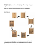
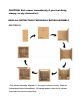
CAUTION: Exit sauna immediately if you feel dizzy, sleepy, or any discomfort. READ ALL INSTRUCTIONS THOROUGHLY BEFORE ASSEMBLY GDI-7289-01 *The above assembly diagram i s for quick reference only. Read all instructions before assembling. All sauna models may not be shown. Parts and accessories may vary.
GDI-7289-01 Schematics *The above assembly diagram i s for quick reference only. Read all instructions before assembling. All sauna models may not be shown. Parts and accessories may vary.
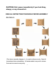
CAUTION: Exit sauna immediately if you feel dizzy, sleepy, or any discomfort. READ ALL INSTRUCTIONS THOROUGHLY BEFORE ASSEMBLY GDI-7389-01 *The above assembly diagram i s for quick reference only. Read all instructions before assembling. All sauna models may not be shown. Parts and accessories may vary.
GDI-7389-01 Schematics *The above assembly diagram i s for quick reference only. Read all instructions before assembling. All sauna models may not be shown. Parts and accessories may vary.
CAUTION: Exit sauna immediately if you feel dizzy, sleepy, or any discomfort. READ ALL INSTRUCTIONS THOROUGHLY BEFORE ASSEMBLY GDI-7689-01 *The above assembly diagram i s for quick reference only. Read all instructions before assembling. All sauna models may not be shown. Parts and accessories may vary.
GDI-7689-01 Schematics *The above assembly diagram i s for quick reference only. Read all instructions before assembling. All sauna models may not be shown. Parts and accessories may vary.
TABLE OF CONTENTS Product Introduction Parts Description Assembly Instructions Control Panel Operation Tips for Using Your Sauna Safety Instructions Safeguards for Your Sauna Warranty Warranty Card 9 9 11 24 26 27 28 29 31 WARNING: Visually inspect all parts before assembly to make sure they are not damaged. Any excessive vibrations during transport could cause damage to the sauna components.
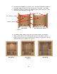
B. The SIDE WALL PANELS are the same size. The LEFT SIDE WALL PANEL on model GDI-7289-01 will have a vent at the top of the wall panel. The RIGHT SIDE WALL PANEL on models GDI-7389-01 and GDI-7689-01 will have a vent at the top of the wall panel. (see Figure 2) VENT LEFT SIDE WALL PANEL CONTROL PANEL RIGHT SIDE WALL PANEL GDI-7289-01 GDI-7389-01/GDI-7689-01 Figure 2 C. The FRONT WALL PANEL can be seen in the images below.
Assembly Instructions A. Choose a good location to install the sauna 1. The location must be dry, leveled, and away from any source of water. 2. The stove must be installed by a certified electrician. 3. Two adults are required for installation on model GDI-7289-01 and three adults for installation on models GDI-7389-01/GDI-7689-01. 4.
Figure 5 C. Installing the LEFT SIDE WALL PANEL to the REAR WALL PANEL 1. Place the LEFT SIDE WALL PANEL up against the REAR WALL PANEL and follow the same instructions used to mount the RIGHT SIDE WALL PANEL to the REAR WALL PANEL. Make sure to use the correct size wood screws when screwing the wall panels together.
Figure 7 D. Installing the FLOOR WOOD GRADE and FRONT WALL PANEL to the LEFT SIDE WALL PANEL and RIGHT SIDE WALL PANEL 1. First, place the FLOOR PANEL on the inside of the sauna room and on your floor (concrete floor is preferred). Two/three adults will be need to install the front wall panel. Be cautious when installing the FRONT WALL PANEL with the stationary glass panels and glass door.
E. Installing the SECOND LAYER BENCH SUPPORT PANEL, FIRST LAYER BENCH SUPPORT PANEL, and FLOOR PANEL 1. Hold the SECOND LAYER BENCH SUPPORT PANEL vertically in place and install it as seen in Figure 9 below. The SECOND LAYER BENCH SUPPORT PANEL is only on model GDI-7689-01. 2. Next, hold the FIRST LAYER BENCH SUPPORT PANEL vertically in place and Install it as seen in Figure 9 below. Also, place FLOOR PANEL in position as well. Use the provided screws to secure the BENCH SUPPORT PANELS into place.
F. Installing the SECOND LAYER BENCH and FIRST LAYER BENCH 1. Slide into position the narrow wood slats that support the SECOND LAYER BENCH (upper bench for model GDI-7689-01 only). (see Figure 11) 2. Next, slide into position the SECOND LAYER BENCH (upper bench for models GDI-7689-01). The screw locations are indicated with arrows for the upper and lower benches. (see Figure 12 & 12a)(Please Note: ONLY INSTALL BENCH ALONG REAR WALL AT THIS TIME) 3. Then slide into position the FIRST LAYER BENCH (lower).
Figure 12a Figure 13 GDI-7289-01 Figure 13a 16
G. Installing the BACKREST ON WALL PANELS 1. Now it is time to install the BACKREST ON REAR WALL PANEL. In addition, you will need to connect the wire connection from the REAR WALL PANEL to the wire connection on the BACKREST ON THE REAR WALL PANEL. After connected, tuck the wires behind the BACKREST. Use the provided screws to screw into place.
Figure 16 H. Installing the FAN SHAPED BENCH, RIGHT SIDE BENCH SUPPORT PANEL, RIGHT SIDE BENCH REINFORCEMENT, and RIGHT SIDE BENCH (only on models GDI7389-01 and GDI-7689-01) 1. You are ready to install the FAN SHAPED BENCH, RIGHT SIDE BENCH SUPPORT PANEL, and RIGHT SIDE BENCH REINFORCEMENT. Be sure to slide into position the narrow wood slats that support the RIGHT SIDE BENCH as seen in Figure 17. Use the provided screws to secure.
Figure 18 2. The RIGHT SIDE BENCH and FAN SHAPED BENCH are ready to be installed.
I. Installing the ROOF PANEL 1. Place the ROOF PANEL over the wall panels carefully. (see Figure 22) 2. Next, carefully slide the ROOF PANEL into place. 3. Use the provided screws to secure the roof into place.
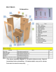
Figure 24 Please Note: Model designs are subject to change. Steam heater must be installed by a certified electrician. J. Installing the Stove Please Note: The stove must be installed by a certified electrician per the manufacturer’s manual. The stove must be installed per the electrical code in your area with reference to the breaker and wire sizes & wire material. Be sure to follow the manufacturer’s manual for proper and safe installation of the stove. 1.
2. The wood housing for the stove will need to be assembled. Use the provided (12) wood screws, 5x40mm, to screw the wood frame together. (see Figure 25 & 26) Figure 25 Figure 26 Please note that the stove installer can mount the wood box frame to the right exterior wall panel once he/she has connected the wiring.
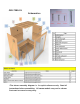
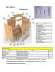
SAUNA CONTROL PANEL - GENERAL INTRODUCTION 1. Description of Functions Functions Touch Key technology FM Radio Reading Lamp Background Lamp and Star Lights Bluetooth Music Play 2. Control System Specifications A.) Rated Voltage: AC100V-AC240V B.) Bluetooth Approximate Effective Distance: 33 feet C.) Rated Power: 50Hz/60Hz 3. LCD Screen displays the following information: 4. Devices controlled by the Control System are: A.) Reading Lamp B.) Background Lamp and Star Lights C.
5. Control Panel Display CONTROL PANEL OPERATION 1. “ “: Powers the unit “ON/OFF”. A.) Press the “ “ to turn the Control Panel “ON”. The LED will display “ “, which means the Control System has powered “ON”. In addition, the Reading Lamp should be “ON” as well. If you press the “ “ once again, the Control Panel will turn “OFF”. B.) The Control System will remain “ON” for 45 minutes. After the 45 minutes has expired, the Control System will turn “OFF”. 2. “ “: Powers the Reading Lamp “ON/OFF”. A.
A.) Press the “ “ to turn on the Background Lamp and Star Lights. The LED will show “ “. Press the “ Star Lights “OFF” and the “ 4. “ “ again to turn the Background Lamp and “ will disappear. “: Powers on the Radio and operates the Bluetooth ( A.) Press the “ ). “ to turn “ON” the FM function of the Radio. The LCD display will show the current frequency. When you press the “ “ again, you will turn on the Bluetooth function allowing you to connect your musical device.
connected to your musical device, the “ “ “ and “ “ and “ “ will stop flashing. If the “ continue to flash, then your musical device has not connected to the Bluetooth. To disconnect your device from the Bluetooth, turn off your device and press “ “ for 3 seconds. F.) To pause the music while your musical device is playing, press “ “ for 3 seconds. Do the same to stop the pause and continue playing music. To play the previous song or next song, you can press “ “ or “ “. G.
body was heated up during the sauna session, it will continue to perspire even after you exit the sauna room. Sit in the sauna with the door open slightly and let your body cool down. Once your body has cooled down and you feel comfortable, you can exit the sauna. After about twenty minutes and when your body has completely cooled down, you can take a shower to rinse the perspiration off your body. Safety Instructions 1.) Read and follow all instructions carefully before using the sauna. 2.
17) Your hands must be dry and free of moisture before plugging and unplugging cords and wiring harnesses from the power supply and circuit boards. Never operate the sauna with wet hands or wet feet to avoid risk of electric shock. Never touch the metal prongs of the plug. 18) Do not attempt to make any repairs yourself without contacting the manufacturer first. If a problem occurs with the sauna, please contact seller, distributor, or the manufacturer to avoid safety risks.
Limited Lifetime Warranty *Limited Lifetime Warranty: Golden Designs, Inc. warranties the sauna room and its attached electronics against defects in material and workmanship for the life of the product from the original date of purchase. This sauna is for indoor use or outdoor use when protected from the outdoor weather elements by a structure that includes a water-proof roof. When not in use and placed outdoors, a water proof cover must be used to cover the sauna room or the warranty will become void.
Since the wood used in construction has been kiln dried, a certain amount of expansion and contraction occurs in the wood in a sauna environment. Disclaimers Golden Designs, Inc. shall not be liable for loss of use of sauna or other Golden Designs, Inc.
WARRANTY CARD Congratulations on your purchase of an Infrared Sauna from Golden Designs, Inc. Please take the time to complete the following Warranty Card and mail it back to: Golden Designs, Inc. 3550 Jurupa Street, Unit B Ontario, CA 91761 Please include a copy of your sales receipt showing date of purchase as this will serve as proof of purchase. Warranty will be VOID if the following warranty card is not mailed back within 60 days of purchase date along with proof of purchase.