Model No. GGEX61707.0 Serial No. Write the serial number in the space above for future reference. Serial Number Decal QUESTIONS? As a manufacturer, we are committed to providing complete customer satisfaction. If you have questions, or if parts are damaged or missing, PLEASE DO NOT CONTACT THE STORE; please contact Customer Care. IMPORTANT: You must note the product model number and serial number (see the drawing above) before contacting us. CALL TOLL-FREE: 1-877-776-4777 Mon.–Fri. 6 a.m.–6 p.m. MST Sat.
TABLE OF CONTENTS WARNING DECAL PLACEMENT . . . . . . . . . . . . . . . . . . . . . . . . . . . . . . . . . . . . . . . . . . . . . . . . . . . . . . . . . . . . . .2 IMPORTANT PRECAUTIONS . . . . . . . . . . . . . . . . . . . . . . . . . . . . . . . . . . . . . . . . . . . . . . . . . . . . . . . . . . . . . . . .3 BEFORE YOU BEGIN . . . . . . . . . . . . . . . . . . . . . . . . . . . . . . . . . . . . . . . . . . . . . . . . . . . . . . . . . . . . . . . . . . . . . .4 ASSEMBLY . . . . . . . . . . . . . .
IMPORTANT PRECAUTIONS WARNING: To reduce the risk of serious injury, read all important precautions and instructions in this manual and all warnings on your exercise cycle before using your exercise cycle. ICON assumes no responsibility for personal injury or property damage sustained by or through the use of this product. 1. Before beginning any exercise program, consult your physician. This is especially important for persons over the age of 35 or persons with pre-existing health problems.
BEFORE YOU BEGIN Congratulations for selecting the new GOLD’S GYM® POWER SPIN 230 R exercise cycle. Cycling is one of the most effective exercises for increasing cardiovascular fitness, building endurance, and toning the body. The POWER SPIN 230 R exercise cycle offers a selection of features designed to let you enjoy this healthful exercise in the convenience and privacy of your home. of this manual. To help us assist you, note the product model number and serial number before contacting us.
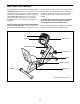
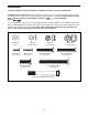
ASSEMBLY To hire an authorized service technician to assemble the exercise cycle, call 1-800-445-2480. Assembly requires two persons. Place all parts of the exercise cycle in a cleared area and remove the packing materials. Do not dispose of the packing materials until assembly is completed. In addition to the included tools, assembly requires your own Phillips screwdriver and an adjustable wrench . As you assemble the exercise cycle, use the drawings below to identify small parts.
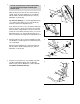
1. 1 To make assembly easier, read the information on page 5 before you begin assembling the exercise cycle. 3 51 While another person lifts the front of the Frame (1) slightly, attach the Front Stabilizer (3) to the Frame with two M10 x 75mm Carriage Bolts (51) and two M10 Nylon Locknuts (63). 1 See the inset drawing. Loosen the Adjustment Knob (17), slide the Rear Frame (2) out of the Frame (1), and then retighten the Adjustment Knob.
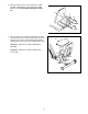
4. Attach the Backrest (5) to the Seat Frame (7) with four M6 x 38mm Button Screws (48) and four M6 Washers (55). Do not tighten the Button Screws yet. 4 5 7 55 48 55 48 5. Have another person hold the Seat Frame (7) under the Rear Frame (2) as shown. Attach the Seat Frame and the Seat (12) to the Rear Frame with four M6 x 42mm Button Screws (49) and four M6 Washers (55). 5 12 See step 3. Tighten the two M8 x 70mm Button Bolts (54). 2 See step 4. Tighten the four M6 x 38mm Button Screws (48).
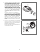
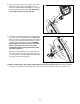
6. The Console (16) can be operated with four 1.5V “D” batteries (not included); alkaline batteries are recommended. IMPORTANT: If the exercise cycle has been exposed to cold temperatures, allow it to warm to room temperature before inserting batteries into the Console. If you do not do this, the console displays or other electronic components may become damaged. Press the tab on the battery cover and remove the battery cover.
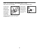
8. Connect the Upper Wire Harness (36) to the Lower Wire Harness (65). Attach the Upright (13) to the Frame (1) with three M8 x 25mm Button Screws (33) and three M8 Split Washers (59). Tip: Avoid pinching the Wire Harnesses during this step. 8 13 36 65 33 33 59 59 1 33 9. Identify the Left Pedal (24), which is marked with an “L” sticker. Using an adjustable wrench, firmly tighten the Left Pedal counterclockwise into the left arm of the Crank (31).
HOW TO OPERATE THE EXERCISE CYCLE HOW TO ADJUST THE SEAT FRAME HOW TO ADJUST THE PEDAL STRAPS For effective exercise, the seat should Seat be in the proper position. As you pedal, there should be a slight bend in your knees when the pedals are in the most forward position. To adjust the Knob seat frame, first loosen the adjustment knob on the frame. Slide the seat frame forward or backward to the desired position. Then, retighten the adjustment knob.
CONSOLE DIAGRAM You can even connect your MP3 player or CD player to the console’s sound system and listen to your favorite music or audio books while you exercise. FEATURES OF THE CONSOLE The advanced console offers an array of features designed to make your workouts more effective and enjoyable. When you use the manual mode of the console, you can change the resistance of the pedals with the touch of a button. As you exercise, the console will provide continuous exercise feedback.
HOW TO USE THE MANUAL MODE The lower right display can show your pedaling speed and the resistance level of the pedals. The display will change modes every few seconds. The display will also show your heart rate when you use the handgrip pulse sensor (see step 5 on page 13). 1. Press any button on the console or begin pedaling to turn on the console. When you turn on the console, the displays and the workout target pacer will light. A tone will then sound and the console will be ready for use. 2.
5. Measure your heart rate if desired. 6. Turn on the fan if desired. If there are Contacts sheets of clear plastic on the metal contacts on the handgrip pulse sensor, remove the plastic. In addition, make sure that your hands are clean. To measure your heart rate, hold the handgrip pulse sensor with your palms resting against the metal contacts. Avoid moving your hands or gripping the contacts tightly.
HOW TO USE A PRESET WORKOUT the center indicator lights, maintain your current speed. IMPORTANT: The workout target pacer is intended only to provide a goal. Make sure to pedal at a speed that is comfortable for you. 1. Press any button on the console or begin pedaling to turn on the console. See step 1 on page 12. 2. Select a preset workout. To select one of the eight preset workouts, press one of the eight buttons on the right and left side of the console.
MAINTENANCE AND TROUBLESHOOTING Inspect and properly tighten all parts of the exercise cycle regularly. Replace any worn parts immediately. With the left side shield removed, locate the Reed Switch (43). Turn the Crank (31) until the Magnet (38) is aligned with the Reed Switch. Next, loosen, but do not remove, the indicated M4 x 16mm Screw (57). Slide the Reed Switch slightly closer to or away from the Magnet, and then retighten the Screw. Turn the Crank for a moment.
EXERCISE GUIDELINES Burning Fat—To burn fat effectively, you must exercise at a low intensity level for a sustained period of time. During the first few minutes of exercise, your body uses carbohydrate calories for energy. Only after the first few minutes of exercise does your body begin to use stored fat calories for energy. If your goal is to burn fat, adjust the intensity of your exercise until your heart rate is near the lowest number in your training zone.
SUGGESTED STRETCHES 1 The correct form for several basic stretches is shown at the right. Move slowly as you stretch—never bounce. 1. Toe Touch Stretch Stand with your knees bent slightly and slowly bend forward from your hips. Allow your back and shoulders to relax as you reach down toward your toes as far as possible. Hold for 15 counts, then relax. Repeat 3 times. Stretches: Hamstrings, backs of knees, and back. 2 2. Hamstring Stretch Sit with one leg extended.
PART LIST—Model No. GGEX61707.0 Key No. Qty. 1 2 3 4 5 6 7 8 9 10 11 12 13 14 15 16 17 18 19 20 21 22 23 24 25 26 27 28 29 30 31 32 33 34 1 1 1 1 1 1 1 1 1 1 2 1 1 1 1 1 1 2 2 1 1 1 1 1 1 1 1 1 1 1 1 1 3 1 Description Key No. Qty.
EXPLODED DRAWING—Model No. GGEX61707.
ORDERING REPLACEMENT PARTS To order replacement parts, please see the front cover of this manual.