
Installation Guide

3
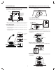
INSTALLATION (Existing Recessed LED Housing)
Housing Inspection
Verify that the existing housing has a compatible quick connector.
Connect and Mount Fixture
Hold the fi xture up to the housing and press the two electrical quick connect
plugs together. Squeeze the two torsion springs to align them with the housing
mounting hooks.
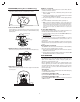
Attach the Fixture to the Housing Hooks
Fit the two torsion springs into the two hooks on the inner downlight housing.
Slide Fixture into Housing
Slide the fi xture up into the housing. The torsions springs will hold the fi xture
securely in place.
Adding to a network:
Refer to your Controller operating instructions to add this fi xture under the
command of the Wireless Controller.
1. With your controller in Discovery or Add Mode, turn the power to the light
fi xture socket ON.
2. You should see an indication on your Controller that the device was added
to the network. The LB65R6Z-1 will fl ash twice.
3. The device will appear in the list of Switches. It should display multi-level
switch.
If the Controller/Gateway shows the addition failed, repeat Steps 1-3.
✓ NOTE: If you have trouble adding the LB65R6Z-1 to a group it may be that the Home
ID and Node ID were not cleared from it after testing. You must fi rst “RESET UNIT” to
remove it from the network. Although adding it to a group includes it in the network,
removing it from a group does not remove it from the network. If removed from a
group, it functions as a repeater (only). “RESET UNIT” removes it completely from
the network.
To Reset Unit (If Required)
In the event that your primary controller is lost or otherwise inoperable, to reset
the fi xture and clear all network information, follow these steps:
1. Use the wall switch to turn the power to the fi xture OFF then ON four times
within four seconds.
2. The LB65R6Z-1 will fl ash twice when the reset occurs.
Before repeating the steps above, try moving the LB65R6Z-1 to a socket in
the same room as the Controller/Gateway in case the preferred socket is out
of range initially.
Repeat Steps 1-3 above until the LB65R6Z-1 is added to the network. Once
the fi xture has been successfully added to the network, move it to the preferred
location.
Removing from a network:
The LB65R6Z-1 can be removed from the network by the Controller/Gateway.
Refer to the Controller operating instructions for details.
1. Set the Controller into Removal Mode, and follow its instruction to delete the
LB65R6Z-1 from the Controller.
2. Reset the fi xture by using the wall switch to turn the power to the fi xture ON.
The LB65R6Z-1 will fl ash twice to confi rm the removal.
BASIC OPERATION
Remote Control Operation
The LB65R6Z-1 can be controlled ON / OFF/ BRIGHT / DIM through wireless
signals from the Z-Wave remote controller or through a gateway via an
application on a smart phone, tablet, or PC.
Once the LB65R6Z-1 has been added to the network,depending on the
functions supported by your controller, it can be assigned to a Group or Scene
and operate when the ALL ON or ALL OFF command is received from the
Controller. It can also be set in Association with another Z-Wave device to
perform a specifi c duty.
Manual Operation
The LB65R6Z-1 can be manually operated using the wall switch while keeping
it on-line with the Z-Wave network.
To manually turn the LB65R6Z-1 ON:
Flip the wall switch OFF then ON. Be sure the switch is ON when fi nished.
To manually turn the LB65R6Z-1 OFF:
Flip the wall switch OFF then ON twice within two seconds. Be sure the switch
is ON when fi nished.
1
Connectors
Squeeze
Torsion Springs
Downlight housing
Ceiling
4
Torsion spring
Hook
Ceiling
Compatible Connector
Ceiling