
Installation & Operation Manual

TST-770 WSD Full Line Manual-RevA
© 2021 Truck System Technologies and Pressure Systems International Inc. All Rights Reserved Worldwide.
support@TSTtruck.com (770) 889-9102 M-F 9-8pm, Sat 9-2pm EST
Page 28
SENSOR PREPARATION - INTERNAL SENSORS
Always consult with a Certied Safety Consultant prior to any installation
procedures. Read and understand all instructions and procedures before
service to components begins.
NOTE: Identify your Internal Sensor type using page 4 image examples and follow
steps 1-4 for your specic sensor. Steps 5-9 are common..
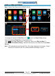
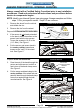
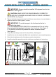
Figure 3: Feed band through sensor
Figure 4: Slide-on internal sensor nal install
SENSOR
PASS BAND
THROUGH HERE
SENSOR
BAND
POSITION SENSOR SO NO MORE THAN ~1 INCH OF
SENSOR BAND EXTENDS BEYOND THE SENSOR.
NOTE: YOU MAY NEED TO ROTATE THE BAND WHILE
HOLDING THE SENSOR AT THE 180º POSITION
FROM THE VALVE STEM TO ACHIEVE THE ~1 INCH
PROTRUSION FROM THE SENSOR
BAND
CLAMP
SCREW
~1”
1. Remove the wheel from the vehicle
and deate the tire.
2. Remove the tire from the wheel.
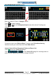
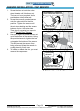
Prepare SCREW-MOUNTED SENSORS:
3. If the sensor is not already attached
to the band, attach the sensor to the
sensor band with the two screws.
Torque the screws to 10-12 in-lbs
(1.1-1.4Nm). See Figure 1.
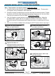
4. Put the sensor and sensor band in
the center position (sometimes
known as the “well”) of the wheel
hub. See Figure 2.
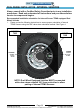
Figure 1: Screw-mounted internal sensor
Figure 2: Screw-mounted Internal sensor nal install
TRIM EXCESS BAND TO LESS
THAN THREE INCHES
SENSOR
BAND
RUBBER
PAD
SENSOR
TORQUE
THE SENSOR
SCREWS TO
10-12 IN-LBS
(1.1-1.4 NM).
SCREW-MOUNTED SENSOR
SCREW-MOUNTED SENSOR
BAND CLAMP SCREW
PASS BAND THROUGH BAND CLAMP
SCREW THEN THROUGH SENSOR
AGAIN TO SECURE EXCESS BAND
SLIDE-ON SENSOR
SLIDE-ON SENSOR
Prepare SLIDE-ON SENSORS:
3. Pass the end of the band through the
sensor and slide sensor to within a
few inches of the band clamp screw.
See Figure 3.
4. Put the sensor and band clamp in the
center position of the wheel hub and
pass the band through the band clamp
screw, then again through the belt-
mounted sensor. See Figure 4.
Back To TABLE OF CONTENTS