
User Manual


gpelectric.com | [page 15]
INSTALLATION
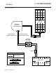
4.6 INSTALLING THE GP-PWM-30 SOLAR CHARGE CONTROLLER
Ensure the Solar Panels are covered. Cover the panel faces completely with an opaque material to stop the
production of electricity when working with panels or wiring – the cardboard shipping boxes are the perfect
option to cover glass surface of the panels.
1.
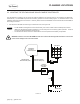
Use the template included in the GP-PWM-30 Manual to mark the four mounting holes and the “cutting line for ush mounting”.
2. Drill the mounting holes
3. Use a keyhole or jig saw to cut along the rectangular outline previously marked
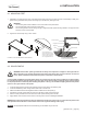
4. Cut the MC4 extension cables to length, allow some excess for strain relief/exibility
5. Use the leftover cable to connect the controller to the batteries ensuring the 30A Fuse is installed as per 4.7. If extra battery
cable is required to connect to the battery bank, Go Power! recommends using an equivalent cable to that supplied with the
kits: 10 Gauge Wire rated to – UL/cUL/USE2.
6. Mount the controller to the wall using the four wood screws provided.
7. Ensure the back of the controller is protected from damage by any object
FIGURE 4-F
FIGURE 4-G
FIGURE 4-H
FIGURE 4-I
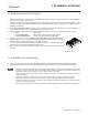
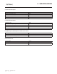
FIGURE 4-E
Battery Bank
PWM 30
Solar Charge
Controller
30A
Battery Bank
PWM 30
Solar Charge
Controller
30A
Battery Bank
PWM 30
Solar Charge
Controller
30A
Battery Bank
PWM 30
Solar Charge
Controller
30A
Battery Bank
PWM 30
Solar Charge
Controller
30A
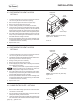
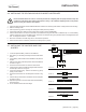
4.7 INSTALLING THE 30A FUSE AND FUSE
HOLDER
1. Locate the positive battery cable from the PWM 30.
2.
Plan where you can safely and easily access the fuse holder
& fuse.
3.
Cut the battery positive cable from the PWM 30 to the planned
lengths.
4. Strip the fuse holder cable and positive cable from PWM 30
as shown in Fig 4-F.
5. Thread the red heat-shrink onto the fuse holder cable
6. Insert the fuse holder and PWM 30 stripped cable ends into
the butt splice as shown in Fig 4-G.
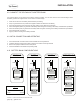
7.
Crimp the butt splice fully - test the connection by gently
pulling on both cables.
8. Thread the heat-shrink over the butt splice as shown in Fig
4-H.
9.
Use the heat gun to shrink the heat shrink over the butt splice
as shown in Fig 4-I.
10.
Repeat the process for the other fuse holder cable & battery
bank connection.
11. Do not install the 30A Fuse at this stage.
Battery Bank
10A
PWM 10
Solar Charge
Controller