RV SOLAR POWER KITS™ User Manual SOLAR EXTREME SOLAR ELITE WEEKENDER ISW OVERLANDER OVERLANDER-E RETREAT RETREAT-E © 2016 Go Power!® By Carmanah Technologies Worldwide Technical Support and Product Information gpelectric.com Carmanah Technologies Corporate Headquarters 250 Bay St, Victoria, BC Canada V9A 3K5 Tel: 1.866.247.
1. Contents 2. GENERAL INFORMATION ����������������������������������������������������������������������������������������������������������4 2.1 HOW DOES A GO POWER! RV SOLAR CHARGING KIT WORK? �������������������������������������������4 2.2 CAUTIONS ����������������������������������������������������������������������������������������������������������������������������������6 2.
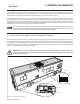
2. GENERAL INFORMATION Congratulations on purchasing your Go Power! RV Solar Kit. You have chosen a clean, quiet and sustainable power source. Go Power! Solar RV Kits allow you to power appliances in your RV, without hooking up to shore power or a noisy generator. Go Power! Solar RV kits will keep your batteries charged, ensuring you have power when you need it. This mobile DC power system allows you to enjoy the luxuries that electricity provides, without a campsite hookup.
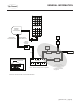
GENERAL INFORMATION Solar Panel Refrigerator Vent Cover or Cable Entry Plate MC4 Red Postive Extension Cable (25 ft) AC Loads MC4 Black Negative Extension Cable (25 ft) AC Panel PWM 30 Solar Charge Controller Inverter Remote Inverter Fuse Transfer Switch Shore Power / Generator Fuse Fuse Legend Battery Bank MC4 Connector Converter / Charger Items Supplied in Weekender, Elite, Extreme Kits Only "CLICK" Note: * All fuse sizes dependant on application For Elite Kit schematic, see page 25.
GENERAL INFORMATION 2.2 CAUTIONS Disconnect all power sources before attempting installation Electricity can be very dangerous. Installation should be performed only by a licensed electrician or qualified personnel. Photovoltaic panels generate DC electricity when exposed to sunlight or other light sources. Contact with the electrically active parts of the panel, such as terminals, can result in burns, sparks and lethal shock whether the panel is connected or disconnected.
GENERAL INFORMATION 2.3 DISCLAIMERS IMPORTANT: Please follow installation and wiring instructions exactly as outlined to ensure safety. We recommend installation by an RV technician or professional electrician to ensure adherence to relevant electrical codes.
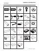
GENERAL INFORMATION 2.4 KIT PARTS Note Please unpack and make sure all parts shown in the list below are included in the kit. If any parts are missing please contact Carmanah’s customer service team at customerservice@carmanah.com or 1.866.247.6527. 1 1 1 2 3 4 4 4 8 12 SOLAR EXTREME 4 SOLAR ELITE 4 WEEKENDER ISW 1 OVERLANDER-E 1 OVERLANDER RETREAT E ITEM # RETREAT 2.4.
GENERAL INFORMATION 1 2 3 4 5 30 6,7 8 9 10 11, 12 13 14 15 16 17 er tick er S p Bum 18 #5 Kit DCGP- 19 20 21 22 #4 Kit DCGP® INVERTER ON/OFF SHORE POWER CHARGER ON/OFF REMOTE SETTINGS UNIT READINGS UNIT SETUP ENTER / SET 23 24 25 26 #3 Kit DCGP- BACK 27 #5 Kit DCGP- #4 Kit DCGP- 28 #3 Kit DCGP- #5 Kit DCGP- 29 DC-Kit #4 GP- 30 gpelectric.
GENERAL INFORMATION 2.5 REQUIRED TOOLS a. Screwdriver (Phillips) h. 1/16” and 3/8” Drill Bits b. Keyhole Saw i. 5/16” & 7/16” Wrench c. Pencil or Marker j. Heat Gun d. Pliers k. Caulking Gun e. Wire Strippers and Cutters l. Sealant f. Butt Splice Crimping Tool m. Digital Multimeter (troubleshooting only) g. Electric Hand Drill n. Torque Driver (optional) Design your solar set up here: [page 10] | gpelectric.
3. PLANNING LOCATIONS 3.1 PLAN YOUR SOLAR SYSTEM SETUP 1. 2. 3. 4. 5. 6. 7. Take a few minutes before commencing any installation work to layout your solar system on paper first. Use the diagrams within this manual (pages 20-27) to help. Complete a simple block diagram identifying the key components and connections of your Solar charging system: Solar Panels, MC4 Positive and Negative Extension Cables, GP-PWM-30 Solar Charge Controller and your Battery Bank as detailed in the diagrams.
PLANNING LOCATIONS 3.3 LOCATING THE GP-PWM-30 AMP SOLAR CHARGE CONTROLLER The GP-PWM-30 is included in all Go Power! RV Solar Kits detailed in this manual except for the expansion kits (Retreat-E, Overlander-E). The GP-PWM-30 provides the necessary protection for the RV battery system. A condensed version of the installation instructions appear in this manual. However, please read the full installation manual included with the GP-PWM-30 Solar Charge Controller. 1.
4. INSTALLATION 4.1 MOUNTING FEET 1. Assemble 4 mounting feet onto each of the solar panels frame using the 1/4” bolts and nuts. This assembly is easily completed on the ground before the panels are brought up to the RV roof. (See Figure 4-A) WARNING: • The mounting feet must be installed on the 4 outer holes in the panel frame. • All 4 mounting feet must be used on a solar panel. • The mounting surface must be strong enough to support the solar panel mounting hardware.
INSTALLATION 4.3 REFRIGERATOR VENT ACCESS OPTION 1 1. 2. 3. 4. 5. 6. 7. 8. Locate the refrigerator vent on the roof of the RV. Remove vent cover to gain access to the duct opening. Drill a hole through the side of the vent (5/8” hole). Remove any sharp edges from the hole. Insert a rubber grommet (not included) into the hole. Insert the MC4 Positive and Negative Extension Cables through the hole and carefully route it to the GP-PWM-30 Solar Charge Controller.
INSTALLATION 4.6 INSTALLING THE GP-PWM-30 SOLAR CHARGE CONTROLLER Ensure the Solar Panels are covered. Cover the panel faces completely with an opaque material to stop the production of electricity when working with panels or wiring – the cardboard shipping boxes are the perfect option to cover glass surface of the panels. 6. 7. Use the template included in the GP-PWM-30 Manual to mark the four mounting holes and the “cutting line for flush mounting”.
INSTALLATION 4.8 CONNECT THE GP-PWM-30 TO BATTERY BANK It is recommended to connect directly to the battery whenever possible. You can also connect to the converter/charger where the battery positive and negative wires connect to the converter/charger 1. 2. 3. 4. 5. 6. 7.
5. MAINTENANCE 5.1 INSPECTION After installing any Go Power! Solar RV Kit or any other Go Power! products it is prudent to complete a periodic check of all electrical and mechanical connections to ensure no connections have become loose or dislodged through transit vibrations. These checks should be carried out at least once after the initial kit installation and the first prolonged RV transit.
6. SPECIFICATIONS CTI-100 Solar Panel Specs Rated power (Pm) 100W Maximum power voltage (Vmp) 18.4V Maximum power current (Imp) 5.43A Open circuit voltage (Voc) 22.6V Short circuit current (Isc) 5.75A CTI-160 Solar Panel Specs Rated power (Pm) 160W Maximum power voltage (Vmp) 18.6V Maximum power current (Imp) 8.6A Open circuit voltage (Voc) 22.5V Short circuit current (Isc) 9.
7. WARRANTY RETURN PROCEDURE The Go Power! warranty is valid against defects in materials and workmanship for the specific product warranty period.
8. SYSTEM DIAGRAMS RETREAT SYSTEM DIAGRAM 100W Solar Panel Refrigerator Vent Cover or Cable Entry Plate MC4 Red Postive Extension Cable (25 ft) MC4 Black Negative Extension Cable (25 ft) PWM 30 Solar Charge Controller 30A Fuse Legend MC4 Connector "CLICK" [page 20] | gpelectric.
SYSTEM DIAGRAMS RETREAT E SYSTEM DIAGRAM 100W Solar Panel 100W Solar Panel Refrigerator Vent Cover or Cable Entry Plate MC4 Red Postive Extension Cable (25 ft) MC4 Black Negative Extension Cable (25 ft) PWM 30 Solar Charge Controller 30A Fuse Legend MC4 Expansion Connector - Negative Battery Bank MC4 Expansion Connector - Postive gpelectric.
SYSTEM DIAGRAMS OVERLANDER SYSTEM DIAGRAM 160W Solar Panel Refrigerator Vent Cover or Cable Entry Plate MC4 Red Postive Extension Cable (25 ft) MC4 Black Negative Extension Cable (25 ft) PWM 30 Solar Charge Controller Fuse Legend MC4 Connector "CLICK" [page 22] | gpelectric.
SYSTEM DIAGRAMS OVERLANDER E SYSTEM DIAGRAM 160W Solar Panel 160W Solar Panel Refrigerator Vent Cover or Cable Entry Plate MC4 Red Postive Extension Cable (25 ft) MC4 Black Negative Extension Cable (25 ft) PWM 30 Solar Charge Controller Fuse Legend MC4 Expansion Connector - Negative Battery Bank MC4 Expansion Connector - Postive gpelectric.
SYSTEM DIAGRAMS WEEKENDER ISW SYSTEM DIAGRAM 160W Solar Panel Refrigerator Vent Cover or Cable Entry Plate MC4 Red Postive Extension Cable (25 ft) AC Loads MC4 Black Negative Extension Cable (25 ft) AC Panel PWM 30 Solar Charge Controller Inverter Remote 1500W Inverter Fuse Legend GP DC Kit 3 Fuse MC4 Connector "CLICK" [page 24] | gpelectric.
SYSTEM DIAGRAMS SOLAR ELITE SYSTEM DIAGRAM 160W Solar Panel 160W Solar Panel Refrigerator Vent Cover or Cable Entry Plate MC4 Red Postive Extension Cable (25 ft) AC Loads MC4 Black Negative Extension Cable (25 ft) AC Panel PWM 30 Solar Charge Controller Inverter Remote 2000W Inverter Charger Fuse Legend GP DC Kit 3 Fuse MC4 Expansion Connector - Negative Shore Power / Generator (with built-in 100A Battery Charger and 50A Transfer Switch) Battery Bank MC4 Expansion Connector - Postive Refer
SYSTEM DIAGRAMS SOLAR EXTREME SYSTEM DIAGRAM 160W Solar Panel 160W Solar Panel 160W Solar Panel Refrigerator Vent Cover or Cable Entry Plate MC4 Red Postive Extension Cable (25 ft) MC4 Black Negative Extension Cable (25 ft) PWM 30 Solar Charge Controller AC Loads AC Panel Inverter Remote 3000W Inverter Fuse Legend GP DC Kit 3 Fuse MC4 Expansion Connector - Negative Fuse Battery Bank MC4 Expansion Connector - Postive [page 26] | gpelectric.
SYSTEM DIAGRAMS TRANSFER SWITCH SYSTEM DIAGRAM AC Panel Shore Power / Generator Use Exisiting Shore Panel to AC Panel Cable Pre-Wired Transfer Switch Line in from Inverter to N.C. Contacts Line in from Converter/Charger to N.O. Contacts Ground Inverter Fuse All positive conductors connected to the battery should be equipped with circuit protection rated to the wire size used Converter / Charger Fuse Battery Bank gpelectric.