
Solar Controller User Manual (GP-PWM-30-UL)
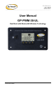


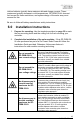
Table Of Contents
- 1.0 Installation Overview
- 2.0 IMPORTANT SAFETY INSTRUCTIONS
- 3.0 Tools and Materials Needed
- 4.0 Choosing a Location
- 5.0 Choosing a Battery
- 6.0 Installation Instructions
- 7.0 Wiring Diagram
- 8.0 Operating Instructions
- 9.0 Display Symbols
- 10.0 Inverter Control (on/off)
- 11.0 USB Charging
- 12.0 Bluetooth® Wireless Technology
- 13.0 Frequently Asked Questions (FAQs)
- 14.0 Troubleshooting Problems
- 15.0 Limited Warranty
- 16.0 Installation Template

GP-PWM-30-UL
_______________________________________________________________________
4
© 2019 Go Power!
1.0 Installation Overview
1.1 Introduction
A Solar Controller (or Charge Controller / Regulator) is an essential component
of your photovoltaic solar system. The Controller maintains the life of the battery
by protecting it from overcharging. When your battery has reached a 100% state
of charge, the Controller prevents overcharging by limiting the current flowing into
the batteries from your solar array.
The GP-PWM-30-UL uses Pulse Width Modulation (PWM) technology and a
unique four stage charging system that includes an optional equalize setting to
charge and protect your battery bank. The GP-PWM-30-UL features an LCD
digital display that shows the charge current of the solar array, system battery
voltage and battery state of charge. The GP-PWM-30-UL also features Maximum
Power Boost Technology™ for manual bulk and absorption charge at any stage
of the charge cycle.
1.2 System Voltage and Current
GP-PWM-30-UL is intended for use at 12 VDC system voltage and is rated for a
maximum continuous DC input current of 37.5A and input voltage of 35VDC.
Per National Electrical Code (NEC) article 690.7 and 690.8, PV module
nameplate ratings must be multiplied by required values (typically 1.25 for both
voltage and current) to obtain the maximum voltage and continuous current
available from the module.
Applying NEC factors, the maximum allowable nameplate PV Panel rated Isc is
30A (30A x 1.25 = 37.5A), and the maximum voltage, Voc is 28VDC (28VDC x
1.25 = 35VDC).
The voltage and current ratings of all equipment connected to PV panels must be
capable of accepting the voltage and current levels available from PV panels
installed in the field.
1.3 Battery Type
The GP-PWM-30-UL is suitable for use with lead acid batteries (vented, GEL, or
AGM type) as well as some lithium iron phosphate (LiFePO
4
) batteries that are
supplied with a Battery Management System (BMS).
1.4 Low Voltage Disconnect Function (USB Port,
Inverter Remote Signal)
To protect the battery against over-discharge this function automatically switches
off the USB output port when Battery 1 voltage is lower than 11.0 VDC. If a