
Solar Controller User Manual (GP-PWM-30-UL)


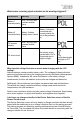
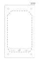
Table Of Contents
- 1.0 Installation Overview
- 2.0 IMPORTANT SAFETY INSTRUCTIONS
- 3.0 Tools and Materials Needed
- 4.0 Choosing a Location
- 5.0 Choosing a Battery
- 6.0 Installation Instructions
- 7.0 Wiring Diagram
- 8.0 Operating Instructions
- 9.0 Display Symbols
- 10.0 Inverter Control (on/off)
- 11.0 USB Charging
- 12.0 Bluetooth® Wireless Technology
- 13.0 Frequently Asked Questions (FAQs)
- 14.0 Troubleshooting Problems
- 15.0 Limited Warranty
- 16.0 Installation Template

GP-PWM-30-UL
_______________________________________________________________________
33
© 2019 Go Power!
Remedy:
Hold down the MAX BOOST Button for approximately 3 seconds to activate
Maximum Power Boost. This will allow the controller to charge batteries to 14.4
+/- 0.1 VDC (14.1 +/- 0.1 VDC Sealed/Gel) with all current the solar array is
producing.
Check all connections from the controller to the array including checking for
correct wire polarity. Check that all connections are clean, tight, and secure.
Continue with the solutions below for additional help on low current readings.
Current Reading: Less than expected
Time of Day: Daytime, clear sunny skies
Possible Causes:
1. Current is being limited below 1 Amp as per normal operation.
2. Incorrect series/parallel configuration and/or wiring connections and/or
wire gauge.
3. Dirty or shaded module or lack of sun.
4. Blown diode in solar module when two or more modules are connected
in parallel.
5. The battery is full.
How to tell:
1. Battery State of Charge screen is close to 100% and the Sun and
Battery icon are present with an arrow in between.
2. Check that the modules and batteries are configured correctly. Check all
wiring connections.
3. Modules look dirty, overhead object is shading modules or it is an
overcast day in which a shadow cannot be cast.
Avoid any shading no matter how small. An object as small as a
broomstick held across the solar module may cause the power
output to be significantly reduced. Overcast days may also cut
the power output of the module.
4. Disconnect one or both array wires from the controller. Take a voltage
reading between the positive and negative array wire. A single 12 volt
module should have an open circuit voltage between 17 and 23 VDC. If
you have more than one solar module, you will need to conduct this test
between the positive and negative terminals of each module junction
box with either the positive or the negative wires disconnected from the
terminal.