
Solar Controller User Manual (GP-PWM-30-UL)
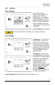

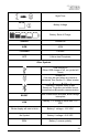
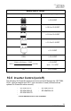

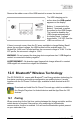


Table Of Contents
- 1.0 Installation Overview
- 2.0 IMPORTANT SAFETY INSTRUCTIONS
- 3.0 Tools and Materials Needed
- 4.0 Choosing a Location
- 5.0 Choosing a Battery
- 6.0 Installation Instructions
- 7.0 Wiring Diagram
- 8.0 Operating Instructions
- 9.0 Display Symbols
- 10.0 Inverter Control (on/off)
- 11.0 USB Charging
- 12.0 Bluetooth® Wireless Technology
- 13.0 Frequently Asked Questions (FAQs)
- 14.0 Troubleshooting Problems
- 15.0 Limited Warranty
- 16.0 Installation Template

GP-PWM-30-UL
_______________________________________________________________________
29
© 2019 Go Power!
13.0 Frequently Asked Questions (FAQs)
Before a problem is suspected with the system, read this section. There are
numerous events that may appear as problems but are in fact perfectly normal.
Please visit https://gpelectric.com/support/
for the most up-to-date FAQs and
troubleshooting videos.
It seems like my flooded batteries are losing water over time.
Flooded batteries may need to have distilled water added periodically to replace
fluid loss during charging. Excessive water loss during a short period of time
indicates the possibility of overcharging or aging batteries.
When charging, my flooded batteries are emitting gas.
During charging, hydrogen gas is generated within the battery. The gas bubbles
stir the battery acid allowing it to receive a fuller state of charge.
Important: Ensure batteries are in a well-ventilated space.
My voltmeter shows a different reading than the GP-PWM-30-UL display.
The meter value on the GP-PWM-30-UL display is an approximate reading
intended for indication purposes only. There is an approximate 0.1 VDC inherent
error present that may be accentuated when compared with readings from
another voltmeter.
There may be a slight difference between the battery voltage displayed on the
GP-PWM-30-UL display and the battery voltage measured at the battery
terminals. When troubleshooting using a voltmeter, check both the battery
voltage at the GP-PWM-30-UL controller terminals and battery voltage at the
battery terminals. If a difference of more than 0.5 VDC is noted, this indicates a
large voltage drop possibly caused by loose connections, long wire runs, small
wire gauge, faulty wiring, a faulty voltmeter or all the above. Consult the
Suggested Minimum Wire Gauge chart in Section 6 for wiring suggestions and
check all connections.
For advanced users:
The GP-PWM-30-UL makes voltage measurement adjustments based on
resistance it detects at the battery terminals. In addition to resistance in the
wires, batteries also have an internal resistance due to chemical properties. The
controller cannot distinguish between these two sources of resistance. It will
compensate up to 250mV in the displayed value.