
Solar Controller User Manual (GP-PWM-30-UL)
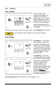

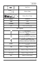
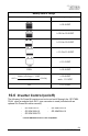

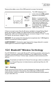
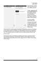


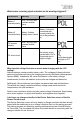
Table Of Contents
- 1.0 Installation Overview
- 2.0 IMPORTANT SAFETY INSTRUCTIONS
- 3.0 Tools and Materials Needed
- 4.0 Choosing a Location
- 5.0 Choosing a Battery
- 6.0 Installation Instructions
- 7.0 Wiring Diagram
- 8.0 Operating Instructions
- 9.0 Display Symbols
- 10.0 Inverter Control (on/off)
- 11.0 USB Charging
- 12.0 Bluetooth® Wireless Technology
- 13.0 Frequently Asked Questions (FAQs)
- 14.0 Troubleshooting Problems
- 15.0 Limited Warranty
- 16.0 Installation Template

GP-PWM-30-UL
_______________________________________________________________________
24
© 2019 Go Power!
Battery State of Charge
Symbol
Battery Voltage
≥ 12.8 VDC
≥ 12.6 to 12.8 VDC
≥ 11.8 to 12.6 VDC
> 11.0 to 11.8 VDC
≤ 11.0 VDC
100% ≥ 12.8 VDC
=
− 11.0
1.8
(100%)
< 12.8 VDC
and > 11.0 VDC
0% ≤ 11.0 VDC
10.0 Inverter Control (on/off)
The following Go Power!® inverters can be turned on/off through the GP-PWM-
30-UL when a modular 6p4c RJ11 type connector is used (included with an
optional Go Power!® inverter remote):
- GP-ISW700-12
- GP-ISW1000-12
- GP-ISW1500-TS
-
- GP-ISW1500-12
- GP-ISW2000-12
*The GP-SW1500 Inverter is not compatible.