
Solar Controller User Manual (GP-PWM-30-UL)
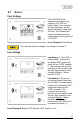

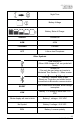
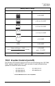

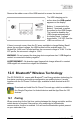


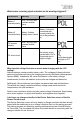
Table Of Contents
- 1.0 Installation Overview
- 2.0 IMPORTANT SAFETY INSTRUCTIONS
- 3.0 Tools and Materials Needed
- 4.0 Choosing a Location
- 5.0 Choosing a Battery
- 6.0 Installation Instructions
- 7.0 Wiring Diagram
- 8.0 Operating Instructions
- 9.0 Display Symbols
- 10.0 Inverter Control (on/off)
- 11.0 USB Charging
- 12.0 Bluetooth® Wireless Technology
- 13.0 Frequently Asked Questions (FAQs)
- 14.0 Troubleshooting Problems
- 15.0 Limited Warranty
- 16.0 Installation Template

GP-PWM-30-UL
_______________________________________________________________________
23
© 2019 Go Power!
Night Time
Battery Voltage
Battery State of Charge
SEALED Sealed/Gel
AGM AGM
FLOODED Flooded
LFP Lithium Iron Phosphate
Other Symbols
USB charger on
(When USB charger is off, no symbol will
show)
Inverter on
(Can only be used when an inverter is
hardwired. See Section 10. When inverter
i ff b l h )
Flashing: Controller ready to pair
Steady-on: Controller and mobile device
connected via Bluetooth
®
communication
BOOST
Max Power Boost activated, Boost charge
incomplete
LOW
Battery 1 / 2 voltage is lower than 11.0
VDC
Whole display will start to blink Battery 1 voltage > 15.5 VDC
No Symbol Battery 2 voltage >15.5 VDC
POL Battery 1 reverse polarity