
Solar Controller User Manual (GP-PWM-30-UL)
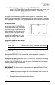
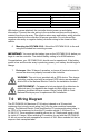

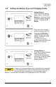
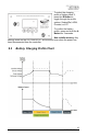
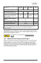
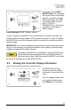
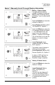
Table Of Contents
- 1.0 Installation Overview
- 2.0 IMPORTANT SAFETY INSTRUCTIONS
- 3.0 Tools and Materials Needed
- 4.0 Choosing a Location
- 5.0 Choosing a Battery
- 6.0 Installation Instructions
- 7.0 Wiring Diagram
- 8.0 Operating Instructions
- 9.0 Display Symbols
- 10.0 Inverter Control (on/off)
- 11.0 USB Charging
- 12.0 Bluetooth® Wireless Technology
- 13.0 Frequently Asked Questions (FAQs)
- 14.0 Troubleshooting Problems
- 15.0 Limited Warranty
- 16.0 Installation Template

GP-PWM-30-UL
_______________________________________________________________________
14
© 2019 Go Power!
WARNING: When the photovoltaic (solar) array is exposed to light, it
supplies a dc voltage to this equipment
AVERTISSEMENT : Lorsque le panneau photovoltaïque (solaire) est
exposé à la lumière, il fournit une tension cc à cet équipement.
8.0 Operating Instructions
8.1 Power Up
When the GP-PWM-30-UL is connected to
the battery, the controller will go into
Power Up mode.
Icons Displayed: All segments of the
numerical display; Backlight blinks
Depending on the battery voltage when
the GP-PWM-30-UL Power Up occurs, the
controller may do a Boost Charge or
quickly go into Float Charge. The Charging Profile selected will commence the
following day after a Power Up (refer to the Charging Profile Chart on page 17-18
for more details).
The fuses or breakers used should be no larger than 50 amps.