
Solar Controller User Manual (GP-PWM-30-UL)
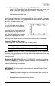

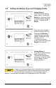
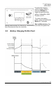
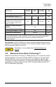
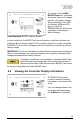
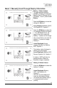
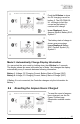
Table Of Contents
- 1.0 Installation Overview
- 2.0 IMPORTANT SAFETY INSTRUCTIONS
- 3.0 Tools and Materials Needed
- 4.0 Choosing a Location
- 5.0 Choosing a Battery
- 6.0 Installation Instructions
- 7.0 Wiring Diagram
- 8.0 Operating Instructions
- 9.0 Display Symbols
- 10.0 Inverter Control (on/off)
- 11.0 USB Charging
- 12.0 Bluetooth® Wireless Technology
- 13.0 Frequently Asked Questions (FAQs)
- 14.0 Troubleshooting Problems
- 15.0 Limited Warranty
- 16.0 Installation Template

GP-PWM-30-UL
_______________________________________________________________________
12
© 2019 Go Power!
Stranded Copper 90°C Wire
Wire Size AWG
Rated Torque (in-lbs)
10
20
8
25
6
35
4
35
With battery power attached, the controller should power up and display
information. Connect the solar wiring to the controller and remove the opaque
material from the solar array. The negative solar array and battery wiring must be
connected directly to the controller for proper operation. Do not connect the
negative solar array or negative battery controller wiring to the chassis of the
vehicle.
6. Mounting the GP-PWM-30-UL. Mount the GP-PWM-30-UL to the wall
using the included four mounting screws.
IMPORTANT: You must set the battery type on the GP-PWM-30-UL before you
begin to use the controller. The default battery setting is for AGM batteries.
Congratulations, your GP-PWM-30-UL should now be operational. If the battery
power is low and the solar array is producing power, your battery should begin to
charge.
7. Re-torque: After 30 days of operation, re-torque all terminal screws to
ensure the wires are properly secured to the controller
WARNING: This unit is not provided with a GFDI device. This charge
controller must be used with an external GFDI device as required by
Article 690 of the National Electric Code for the installation location.
AVERTISSEMENT : Cet appareil n’est pas équipé d’un détecteur de
défaut de terre. Ce régulateur de charge doit être utilisé avec un
détecteur de défaut de terre comme l’exige l’article 690 du Code
National Électrique pour l’emplacement de l’installation.
7.0 Wiring Diagram
The GP-PWM-30-UL Maximum 37.5A rating is based on a 30-amp total
maximum short circuit current rating (Isc) from the solar modules nameplate
ratings. The National Electric Code specifies the PV equipment/system rating to
be 125% of the maximum Isc from the PV module ratings (1.25 times 30 =
37.5A). E.G. Three modules in parallel with an Isc of 7 amps each equal a total
Isc input of 21 amps. When selecting PV modules for use with the GP-PWM-30-
UL do not exceed a total nameplate Isc current of 30A. Solar modules list the Isc
amps on their nameplate label.