
User Manual


[page 22] | gpelectric.com
5.3 BATTERY
WARNING: Before starting this section ensure the circuit breaker is in the off position.
Ensure that correct polarity is being observed when making connections to the batteries. Serious damage
to equipment could result if these instructions are not followed exactly.
1.
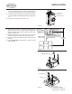
Connect the negative (black) cable from the GP-MPPT-PRO-60 to the battery’s negative terminal. Connect the positive (red)
cable from the circuit breaker to the battery’s positive terminal. Tighten according to the battery manufacturer’s recommen-
dations.
The individual batteries must be connected together before the connection to the GP-MPPT-PRO-60 is made. (See
Figure 5-G for typical battery congurations). Go Power! recommends the use of the Go Power! GP-AGM-100-12V or
GP-AGM-224-6V batteries with this kit.
2. The GP-MPPT-PRO-60 will now be powered.
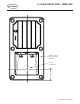
Note
GP-
MPPT-
40
80A Circuit Breaker
Ring
Terminal
Legend
Ring
Terminal
Cable
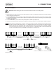
Configuration 1:
6 x 12V 100Ah Batteries
Configuration 2:
6 x 6V 224Ah Batteries
12 V
6 V 6 V 6 V
6 V 6 V 6 V
12 V
12 V
12 V
12 V
12 V
80A Circuit Breaker
GP-
MPPT-
40
FIGURE 5-G: TYPICAL BATTERY BANK CONFIGURATIONS
CONNECTIONS