
User Manual


[page 20] | gpelectric.com
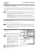
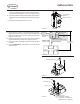
5.1 SOLAR PANELS
WARNING: Before starting this section ensure the solar disconnect is in the off position.
5. CONNECTIONS
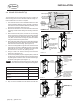
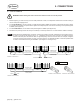
FIGURE 5-C: MC4 NEGATIVE FIGURE 5-D: MC4 POSITIVE
Should not
exceed 10 ft
Should not
exceed 25 ft
Air ConditionerAir Conditioner
170W
Solar Panel
170W
Solar Panel
Battery Bank
A minimum of 6 batteries / 600 Ah
battery bank is recommended for this kit.
(not included)
GP-
CEP-
25
8 ft Battery Cable
4 AWG (Included)
GP-
MPPT-
40
Solar Disconnect
GP-
MPPT-
40
Circuit Breaker
1 ft Parallization Cable
4 AWG, Cut from 9 ft Battery Cable
25 ft Solar Cable
10 AWG (Included)
10 ft Extension Cable
10 AWG (Included)
10 ft Extension Cable
10 AWG (Included)
3 ft Extension Cable
10 AWG (Included)
3 ft Extension Cable
10 AWG (Included)
GP-MPPT-R
Remote
170W
Solar Panel
170W
Solar Panel
170W
Solar Panel
170W
Solar Panel
Cable Entry Plate
Solar Controller
Solar Controller
SOLAR-AE6
only
GP-
CEP-
25
Solar Disconnect
Cable Entry Plate
25 ft Solar Cable
10 AWG (Included)
REV
ECO #
DESCRIPTION
DATE
DRAWN BY
A
- -
D
C
B
A
A
B
C
D
1
2
3
4
5
6
7
8
8
7
6
5
4
3
2
1
TITLE
B
1:33.3
A
1 OF 4
SHEET
SIZE
REVISION
SCALE
DRAWING NO
CAD REFERENCE
VALTERRA
PRODUCTS, LCC.
(GO POWER!)
201 - 710 REDBRICK STREET
VICTORIA, BC CANADA V8T 5J3
Tel [866] 247-6527
Fax [866] 607-6527
THE INFORMATION CONTAINED IN
THIS DRAWING IS THE SOLE
PROPERTY OF VALTERRA
PRODUCTS, LCC. (GO POWER!).
ANY REPRODUCTION IN PART OR
AS A WHOLE WITHOUT THE
WRITTEN PERMISSION OF
VALTERRA PRODUCTS, LCC. (GO
POWER!) IS PROHIBITED.
PROPRIETARY
ORIGINALLY DESIGNED BY
ORIGINALLY DRAWN BY
CHECKED BY
DATE
DATE
DATE
UNLESS OTHERWISE SPECIFIED
DO NOT SCALE DRAWING
INTERPRET DIMENSIONS AND TOLERANCES
PER ASME Y14.100-2000
TOLERANCES APPLY AS SHOWN BELOW
DECIMALS SURF FINISH ANGLES
X
X.X
X.XX
X.XXX
± 2.5
± .25
± .10
± .01
1
METRIC
THIRD ANGLE PROJECTION
DOC #
DATE
2017-11-09
102
A
DOC REVISION
AE
ALL COMPONENTS AND PROCESSES TO BE ROHS COMPLIANT, CERTIFICATE REQUIRED WITH INITIAL SHIPMENT
1.5 μm
FIGURE 5-A: SOLAR-AE-6
Should not
exceed 10 ft
Should not
exceed 25 ft
Air Conditioner
170W
Solar Panel
170W
Solar Panel
Positive
Solar Controller
Cable Entry Plate
Negative
170W
Solar Panel
170W
Solar Panel
Remote
GP-MPPT-R
3 ft Extension Cable
10 AWG (Included)
10 ft Extension Cable
10 AWG (Included)
25 ft Solar Cable
10 AWG (Included)
Circuit Breaker
GP-
MPPT-
40
Solar Disconnect
8 ft Battery Cable
4 AWG (Included)
GP-
CEP-
25
A minimum of 6 batteries / 600 Ah
battery bank is recommended for this kit.
(not included)
Battery Bank
D
C
B
A
A
B
C
D
1
2
3
4
5
6
7
8
8
7
6
5
4
3
2
1
TITLE
B
1:33.3
A
2 OF 3
SHEET
SIZE
REVISION
SCALE
DRAWING NO
CAD REFERENCE
VALTERRA
PRODUCTS, LCC.
(GO POWER!)
201 - 710 REDBRICK STREET
VICTORIA, BC CANADA V8T 5J3
Tel [866] 247-6527
Fax [866] 607-6527
THE INFORMATION CONTAINED IN
THIS DRAWING IS THE SOLE
PROPERTY OF VALTERRA
PRODUCTS, LCC. (GO POWER!).
ANY REPRODUCTION IN PART OR
AS A WHOLE WITHOUT THE
WRITTEN PERMISSION OF
VALTERRA PRODUCTS, LCC. (GO
POWER!) IS PROHIBITED.
PROPRIETARY
ORIGINALLY DESIGNED BY
ORIGINALLY DRAWN BY
CHECKED BY
DATE
DATE
DATE
UNLESS OTHERWISE SPECIFIED
DO NOT SCALE DRAWING
INTERPRET DIMENSIONS AND TOLERANCES
PER ASME Y14.100-2000
TOLERANCES APPLY AS SHOWN BELOW
DECIMALS SURF FINISH ANGLES
X
X.X
X.XX
X.XXX
± 2.5
± .25
± .10
± .01
1
METRIC
THIRD ANGLE PROJECTION
DOC #
DATE
2017-11-09
102
A
DOC REVISION
AE
ALL COMPONENTS AND PROCESSES TO BE ROHS COMPLIANT, CERTIFICATE REQUIRED WITH INITIAL SHIPMENT
1.5 μm
FIGURE 5-B: SOLAR-AE-4
Legend
MC4
Connector
1. Before beginning you must securely cover the solar panels with a solid, non-transparent material. We recommend that you
use the solar panel shipping boxes.
2. For the SOLAR-AE6 kit, connect 2 strings of 3 solar panels together in series. This means 3 solar panels are to be in series
by connecting the positive of one panel to the negative of an adjacent panel. Connect the remaining 3 solar panels together
in series. (See Figure 5-A).
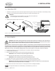
3. For the SOLAR-AE4 kit, connect all the solar panels together in series. (See Figure 5-B).
4. Recall from the planning section that it may be necessary to use the provided 3’ or 10’ solar extension cables for this step.
Solar panels use polarized MC4 connectors, meaning the positive connector is dierent than the negative connec-
tor. Each connector has its polarity symbol (+ or -) embossed near the end of the connector. This polarity symbol is
relative to the solar panel. To extend a cable, an opposite polarity connector must be used. For example, a negative
connector must plug into a positive connector in order to extend it. It is advisable to attach or mark the positive cable
in order to avoid confusion during the installation. (See Figure 5-C and Figure 5-D).
Note