
User Manual


[page 18] | gpelectric.com
INSTALLATION
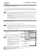
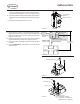
4.5 BATTERY CIRCUIT BREAKER
The circuit breaker is a safety device designed to protect the
battery cables from high over-current faults.
1.
The circuit breaker must be mounted on the positive (red)
cable between the GP-MPPT-PRO-60 charge controller and
the batteries. (See Figure 4-N)
The circuit breaker should be mounted as close to
the batteries as possible. Go Power! recommends
using the 2 ft. positive (red) cable between the circuit
breaker and the battery bank.
2. Using 3 of #10 x 3/4” screws included, securely mount the
circuit breaker. (See Figure 4-O).
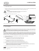
3.
Assemble the ring lugs of the positive (red) cables to the
circuit breaker. (See Figure 4-P).
4. Tighten the nuts holding the ring lugs to 75 in. lbs.
5. Connect the bare end of the 8 ft. positive (red) cable to the
GP-MPPT-PRO-60 charge controller. Cut excess cable length
as required. Follow the GP-MPPT-PRO-60 User Manual for
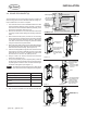
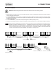
Note
Should not
exceed 10 ft
Should not
exceed 25 ft
Air ConditionerAir Conditioner
170W
Solar Panel
170W
Solar Panel
Battery Bank
GP-
CEP-
25
8 ft Battery Cable
4 AWG (Included)
GP-
MPPT-
PRO-60
Solar Disconnect
GP-
MPPT-
80A Circuit Breaker
1 ft Parallization Cable
4 AWG, Cut from 9 ft Battery Cable
25 ft Solar Cable
10 AWG (Included)
10 ft Extension Cable
10 AWG (Included)
10 ft Extension Cable
10 AWG (Included)
3 ft Extension Cable
10 AWG (Included)
3 ft Extension Cable
10 AWG (Included)
GP-MPPT-PRO-R
Remote
170W
Solar Panel
170W
Solar Panel
170W
Solar Panel
170W
Solar Panel
Cable Entry Plate
Solar Controller
(Primary)
Solar Controller
(Secondary)
SOLAR-AE6
only
GP-
CEP-
25
Solar Disconnect
Cable Entry Plate
25 ft Solar Cable
10 AWG (Included)
REV
ECO #
DESCRIPTION
DATE
DRAWN BY
A
- -
D
C
B
A
A
B
C
D
1
2
3
4
5
6
7
8
8
7
6
5
4
3
2
1
TITLE
B
1:33.3
A
1 OF 4
SHEET
SIZE
REVISION
SCALE
DRAWING NO
CAD REFERENCE
VALTERRA
PRODUCTS, LCC.
(GO POWER!)
201 - 710 REDBRICK STREET
VICTORIA, BC CANADA V8T 5J3
Tel [866] 247-6527
Fax [866] 607-6527
THE INFORMATION CONTAINED IN
THIS DRAWING IS THE SOLE
PROPERTY OF VALTERRA
PRODUCTS, LCC. (GO POWER!).
ANY REPRODUCTION IN PART OR
AS A WHOLE WITHOUT THE
WRITTEN PERMISSION OF
VALTERRA PRODUCTS, LCC. (GO
POWER!) IS PROHIBITED.
PROPRIETARY
ORIGINALLY DESIGNED BY
ORIGINALLY DRAWN BY
CHECKED BY
DATE
DATE
DATE
UNLESS OTHERWISE SPECIFIED
DO NOT SCALE DRAWING
INTERPRET DIMENSIONS AND TOLERANCES
PER ASME Y14.100-2000
TOLERANCES APPLY AS SHOWN BELOW
DECIMALS SURF FINISH ANGLES
X
X.X
X.XX
X.XXX
± 2.5
± .25
± .10
± .01
1
METRIC
THIRD ANGLE PROJECTION
DOC #
DATE
2017-11-09
102
A
DOC REVISION
AE
ALL COMPONENTS AND PROCESSES TO BE ROHS COMPLIANT, CERTIFICATE REQUIRED WITH INITIAL SHIPMENT
1.5 μm
PRO-60
FIGURE 4-Q
additional details and recommended torque and strip lengths.
6.
Connect the bare end of the 10 ft. negative (black) cable to the GP-MPPT-PRO-60 charge controller. Cut excess cable length
as required. Follow the GP-MPPT-PRO-60 User Manual for additional details and recommended torque and strip lengths.
7. Use the included tie-wraps to secure the cables together.
• This helps reduces the amount of electronic noise radiated by the kit.
• Ensure these paired cables run through the same hole(s) as they are routed.
8. Use the 3/8” white cable clamps to secure the cable to the RV.
4.6 GP-MPPT-PRO-60 CHARGE CONTROLLER
You will need the GP-MPPT-PRO-60 User Manual included in the kit to complete installation
1. The GP-MPPT-PRO-60 charge controller should be mounted within 10’ of the battery for optimal operation. The GP-MPPT-
PRO-60 is designed to be mounted vertically on the side of a wall in a weather tight enclosure.
The GP-MPPT-PRO-60 must be mounted indoors in a dry location - such as inside the battery compartment.
2. Follow the GP-MPPT-PRO-60 installation section in the User Manual.
3. Cut any excess length from the positive (red) and negative (black) 10 AWG solar cables, if required.
4. Strip 1/2” of insulation from the positive end the solar cable coming from the disconnect.
5. Insert the stripped end of the positive cable coming from the solar disconnect into the solar positive (PV+) terminal of the
primary GP-MPPT-PRO-60.
6. Repeat steps 5-6 for the negative (black) solar cable coming from the solar disconnect, but inserting the stripped end into
the solar negative (PV-) terminal of the primary GP-MPPT-PRO-60.
7. For the SOLAR-AE4 kit, skip steps 8-15.
8.
For the SOLAR-AE6 kit, repeat steps 3-6 for the second set of cables coming from the second CEP to the second GP-
MPPT-PRO-60.
Note
Note
Note