
User Manual


gpelectric.com | [page 15]
INSTALLATION
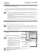
4.3 CABLE ENTRY PLATE(S)
1.
Use the included tie-wraps to secure the cables together
approximately every 5’.
•
This helps reduce the amount of electrical noise
radiated by the kit.
•
Ensure these paired cables run through the same
hole(s) as they are routed through the interior
of the RV.
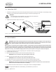
2.
Mark the location of the CEP cable hole to be drilled for
feeding the cables through the snap bushing and the RV
roof – details on install below.
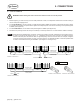
3.
When the CEP is installed the hole for the cables should
be along its center line and approximately 1.25” from the
back edge. (See Figure 9-A drill template).
4.
Mark the location of the CEP cable hole to be drilled for
feeding the cables through the snap bushing and the RV
roof – details on install below. (See Figure 4-C).
5.
Drill a small pilot hole in the chosen spot. Using the hole
saw enlarge the hole to be 3/4” in diameter.
6.
Remove any sharp edges from the hole and install the
snap bushing.
7.
Thoroughly clean the RV roof around the hole in the area the
CEP will be mounted. A clean surface is critical to ensuring
a watertight seal.
8.
Feed wires down through the snap bushing in the hole until
they reach the charge controller mounting location.
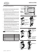
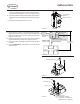
9. Apply a generous bead of sealant to the underside of the
CEP following the channel provided and around all mount-
ing holes.
The sealant should expand signicantly beyond the
bottom of the CEP.
10. Lower the CEP down until just the tip of the caulking gun
ts under the CEP. Apply a generous bead into and around
the cable hole including the cable as well. (See Figure 4-D).
11. Finish lowering the CEP on the RV roof.
12.
Dispense a generous dab of sealant into each mounting
hole.
13. Using the 6 of #10 x 1” screws provided, secure the CEP
to the RV roof – through the sealant and into the roof. (See
Figure 4-E).
Do not over-tighten screws.
14.
Apply a dab of sealant on top of and around the head of
each screw.
15.
Apply another generous bead of sealant around the pe-
rimeter of the CEP.
16.
Secure the exposed solar panel cables using the cable
clamps provided.
17. For the SOLAR-AE6 kit, repeat steps 1-15 for the second
CEP.
Note
Note
Note
FIGURE 4-B
FIGURE 4-D
1.25"
Drill Hole
(.75" Diameter)
Sealant Channel on
underside of Cable
Entry Plate
Underside channels guide
adhesive dispensing around
screws, drill hole and CEP
perimeter
Connector Cables
Cable Entry Plate
Apply sealant around
CEP perimeter and in
all screw holes before
and after installation
CEP Mounting
Screws (x6)
Lower CEP down with
enough clearance to
apply sealant around
cables feeding through
drill hole
Snap Bushing
Drill Hole
for Cables
RV Roof
NOTES
1
TYPE YOUR NOTES IN HERE
2
FEEL FREE TO MOVE/RESIZE THIS TABLE
REV
ECO #
DESCRIPTION
DATE
DRAWN BY
MATERIAL
SEE PART MATERIAL
FINISH
N/A
FINISH
SPEC
N/A
COLOR
N/A
D
C
B
A
A
B
C
D
1
2
3
4
5
6
7
8
8
7
6
5
4
3
2
1
TITLE
B
1:2
-
CABLE ENTRY PLATE ASSY
1 OF 2
74654
SHEET
SIZE
REVISION
SCALE
DRAWING NO
CAD REFERENCE
Carmanah Technologies Corp.
250 Bay Street
Victoria, BC Canada V9A 3K5
Tel [250] 380-0052
Fax [250] 380-0062
CHANGES SHALL BE INCORPORATED
ELECTRONICALLY BY THE DESIGN AUTHORITY
PDM MAINTAINED DATA
COPYRIGHT © 2012 BY
Carmanah Technologies Corp. Victoria, BC, Canada
ALL RIGHTS RESERVED. NO PART OF THIS
DOCUMENT MAY BE REPRODUCED STORED IN A
RETRIEVAL SYSTEM, OR TRANSMITTED IN ANY
FORM, WITHOUT THE WRITTEN PERMISSION OF
Carmanah Technologies Corp.
PROPRIETARY
ORIGINALLY DESIGNED BY
ORIGINALLY DRAWN BY
CHECKED BY
DATE
DATE
DATE
Taylor Townsend
Taylor Townsend
07/31/2015
UNLESS OTHERWISE SPECIFIED
DO NOT SCALE DRAWING
INTERPRET DIMENSIONS AND TOLERANCES
PER ASME Y14.100-2000
TOLERANCES APPLY AS SHOWN BELOW
DECIMALS SURF FINISH ANGLES
.X
.XX
.XXX
.XXXX
± .1
± .01
± .005
± .0005
63
1
INCHES
THIRD ANGLE PROJECTION
DOC #
DATE
21/12/11
57012
B
DOC REVISION
74654
ALL COMPONENTS AND PROCESSES TO BE ROHS COMPLIANT, CERTIFICATE REQUIRED WITH INITIAL SHIPMENT
FIGURE 4-E
FIGURE 4-C