
User Manual


[page 12] | gpelectric.com
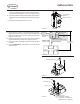
Should not
exceed 10 ft
Should not
exceed 25 ft
Air ConditionerAir Conditioner
170W
Solar Panel
170W
Solar Panel
Battery Bank
GP-
CEP-
25
8 ft Battery Cable
4 AWG (Included)
GP-
MPPT-
PRO-60
Solar Disconnect
GP-
MPPT-
80A Circuit Breaker
1 ft Parallization Cable
4 AWG, Cut from 9 ft Battery Cable
25 ft Solar Cable
10 AWG (Included)
10 ft Extension Cable
10 AWG (Included)
10 ft Extension Cable
10 AWG (Included)
3 ft Extension Cable
10 AWG (Included)
3 ft Extension Cable
10 AWG (Included)
GP-MPPT-PRO-R
Remote
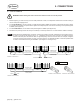
170W
Solar Panel
170W
Solar Panel
170W
Solar Panel
170W
Solar Panel
Cable Entry Plate
Solar Controller
(Primary)
Solar Controller
(Secondary)
SOLAR-AE6
only
GP-
CEP-
25
Solar Disconnect
Cable Entry Plate
25 ft Solar Cable
10 AWG (Included)
REV
ECO #
DESCRIPTION
DATE
DRAWN BY
A
- -
D
C
B
A
A
B
C
D
1
2
3
4
5
6
7
8
8
7
6
5
4
3
2
1
TITLE
B
1:33.3
A
1 OF 4
SHEET
SIZE
REVISION
SCALE
DRAWING NO
CAD REFERENCE
VALTERRA
PRODUCTS, LCC.
(GO POWER!)
201 - 710 REDBRICK STREET
VICTORIA, BC CANADA V8T 5J3
Tel [866] 247-6527
Fax [866] 607-6527
THE INFORMATION CONTAINED IN
THIS DRAWING IS THE SOLE
PROPERTY OF VALTERRA
PRODUCTS, LCC. (GO POWER!).
ANY REPRODUCTION IN PART OR
AS A WHOLE WITHOUT THE
WRITTEN PERMISSION OF
VALTERRA PRODUCTS, LCC. (GO
POWER!) IS PROHIBITED.
PROPRIETARY
ORIGINALLY DESIGNED BY
ORIGINALLY DRAWN BY
CHECKED BY
DATE
DATE
DATE
UNLESS OTHERWISE SPECIFIED
DO NOT SCALE DRAWING
INTERPRET DIMENSIONS AND TOLERANCES
PER ASME Y14.100-2000
TOLERANCES APPLY AS SHOWN BELOW
DECIMALS SURF FINISH ANGLES
X
X.X
X.XX
X.XXX
± 2.5
± .25
± .10
± .01
1
METRIC
THIRD ANGLE PROJECTION
DOC #
DATE
2017-11-09
102
A
DOC REVISION
AE
ALL COMPONENTS AND PROCESSES TO BE ROHS COMPLIANT, CERTIFICATE REQUIRED WITH INITIAL SHIPMENT
1.5 μm
PRO-60
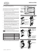
FIGURE 3-A
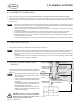
3.1 PLACEMENT OF SOLAR PANELS
1. Remove all solar panels from their boxes. Set aside the boxes as they will be used in the instructions to follow.
2. Using the solar panel boxes as placeholders, plan the layout of the panels on your RV rooftop. Once you have positioned
the boxes correctly, leave the boxes on the RV roof as place holders until the panels are installed. (See Figure 2-B for a
sample layout).
• Placement of the panels should be as close together as possible. Each panel has 3.3’ of cable coming from the
junction box. It may be necessary to use the included solar panel extension cables. If required, longer extension
cables can be purchased. Please contact your dealer to purchase.
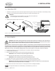
• Select a location where the mounting surface is at least 1/2” thick and strong enough to support the solar panel
mounting hardware.
• Solar panels should be located a minimum of 3’ from the front of the RV to reduce wind load on the panels.
• Avoid internal wiring when selecting the solar panel mounting locations for drilling the mounting holes.
• Ensure xed obstacles, such as air conditioners, will not shade the solar panels. (Shading can greatly reduce the
performance of the solar system).
•
Ensure there is enough room to access the panels and other xed obstacles for future inspection and maintenance.
Note
3. PLANNING LOCATIONS
3.2 CABLE ENTRY PLATE(S)
1. Plan where the Cable Entry Plate(s) (CEP) will be located on the RV roof.
•
Make sure it is within reach of the solar panels. It may be necessary to use the included extension cables to reach
the CEP(s). If required, longer extension cables can be purchased. Please contact your dealer to purchase.
•
Make sure the CEP location(s) is also accessible from the interior of the RV to route the cables to the charge
controller.
• The GP-MPPT-PRO-60 charge controller(s) should be placed no more than 25’ from the CEP(s). Closer is better
to reduce the voltage loss due to resistance.
Note
3.3 GP-MPPT-PRO-60 CHARGE CON-
TROLLER
1.
Plan where the GP-MPPT-PRO-60 charge controller(s) will
mount, see Figure 3-A for more detail including maximum
distances.
•
The GP-MPPT-PRO-60 is designed to be mount-
ed vertically in an indoor location inside a weath-
erproof enclosure.
•
The GP-MPPT-PRO-60 weighs approximately
2.6lbs. – ensure the mounting location will hold
this weight.
•
The location will need access to the cables ends
from the CEP, the battery compartment and the
GP-MPPT-PRO-R remote cable.
• The SOLAR-AE6 includes a second GP-MPPT-
PRO-60 to be connected in parallelization mode
to allow for 80A charging.
WARNING: Failure to secure the GP-MPPT-
PRO-60 could cause it to become dislodged
while the RV is underway and cause severe
damage to the unit and/or the RV.
Note