GP-SWR-A Remote ________________________________________________ Owner’s Manual
GP‐SWR‐A ___________________________________________________________ Table of Contents Features 2 Specification 3 Introduction 3 Installation 6 Repair and Return Information 7 Mounting the Remote 7 1.0 Features The SWR-A Remote allows the switching on and off of the inverter from a remote location.
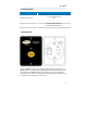
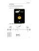
GP‐SWR‐A ___________________________________________________________ 2.0 Specifications SPECIFICATIONS Input Voltage Range Operating Temperature Range Storage Temperature Range Standby Current Draw Applicable Models Efficiency GP-SWR-A REMOTE 10.5-60VDC (Based on the battery input voltage of the inverter—it can be used for 12V, 24V and 48V inverters) 0-40°C -30°C – 70°C <40 mA GPSW-150/GPSW-300/GPSW-600/ GPSW-1500/GPSW-2000/GPSW-3000 85-90% 3.0 Introduction This is an ON/OFF remote control.
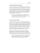
GP‐SWR‐A ___________________________________________________________ 3.1 Reverse Override Function (ROF) In some RV’s, a TV monitor is used in conjunction with a camera which allows the driver to view the area behind the vehicle while reversing. If the TV monitor is in view of the driver, it should remain off, and should only be turned on when the vehicle is reversing.
GP‐SWR‐A ___________________________________________________________ The wire feeding the “+” battery voltage signal to the ¼” connector for the ROF or Ignition Lockout functions should have a 0.5A fuse in series for protection. 3.3 Selecting ROF or Ignition Lockout Functions Jumper JP1 is placed inside the remote control and is used to select either Reverse Override Function or Ignition Lockout Function (open the back cover for access to the jumper JP-1).
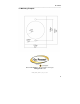
GP‐SWR‐A ___________________________________________________________ 4.0 Installation 1. Refer to the drawing for hole and cutout dimensions. 2. Use the cable between CR8 remote and the inverter. 3. Switch the inverter to REMO position. 4.
GP‐SWR‐A ___________________________________________________________ 5.0 Repair and Return Information Visit www.gpelectric.com to read the “frequently asked questions” section of our website to troubleshoot the problem. If trouble persists: 1. Call your Go Power!™ Technical Support team (1-866-247-6527). 2. Return defective product to place of purchase 6.0 Mounting the Remote Step 1- Cut out the template (on page 8) attached and position it on the wall where the remote is to be mounted.
GP‐SWR‐A ___________________________________________________________ 6.1 Mounting Template © 2011 GO POWER!™ By Carmanah Technologies www.gpelectric.