
User Manual

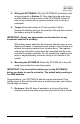
Table Of Contents

GP-PWM-30
________________________________________________________________________
9
4. Wiring the GP-PWM-30. Wire the GP-PWM-30 according to the
wiring schematic in Section 11. Run wires from the solar array
and the batteries to the location of the GP-PWM-30. Keep the
solar array covered with an opaque material until all wiring is
completed.
5. Torque all terminal screws to 16 inch pounds (1.8N.m).
Connect the battery wiring to the controller first and then connect
the battery wiring to the battery.
IMPORTANT: Always use appropriate circuit protection on an
y
conductor attached to a battery.
With battery power attached, the controller should power up and
display information. Connect the solar wiring to the controller and
remove the opaque material from the solar array. The negative
solar array and battery wiring must be connected directly to the
controller for proper operation. Do not connect the negative solar
array or negative battery controller wiring to the chassis of the
vehicle.
6. Mounting the GP-PWM-30. Mount the GP-PWM-30 to the w
all
using the included four mounting screws.
IMPORTANT: You must set the battery type on the GP-PWM-30
before you begin to use the controller. The default battery setting is
for AGM batteries.
Congratulations, your GP-PWM-30 should now be operational. If the
battery power is low and the solar array is producing power, your battery
should begin to charge.
7. Re-torque: After 30 days of operation, re-torque all terminal
screws to ensure the wires are properly secured to the
controller.
© 2018 Go Power! By Valterra Power