Solar Controller GP-PWM-30 Owner’s Manual 1 © 2018 Go Power! By Valterra Power
GP-PWM-30 ________________________________________________________________________ 2 © 2018 Go Power! By Valterra Power
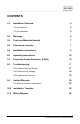
GP-PWM-30 ________________________________________________________________________ CONTENTS 1.0 Installation Overview 4 1.1 Introduction 4 1.2 Specifications 5 2.0 Warnings 6 3.0 Tools and Materials Needed 7 4.0 Choosing a Location 7 5.0 Installation Instructions 8 6.0 Operating Instructions 10 7.0 Frequently Asked Questions (FAQs) 16 8.0 Troubleshooting 17 8.1 Problems with the Display 17 8.2 Problems with Voltage 18 8.3 Problems with Current 18 Limited Warranty 20 9.
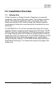
GP-PWM-30 ________________________________________________________________________ 1.0 Installation Overview 1.1 Introduction A Solar Controller (or Charge Controller / Regulator) is an essential component of your photovoltaic solar system. The Controller maintains the life of the battery by protecting it from overcharging. When your battery has reached a 100% state of charge, the Controller prevents overcharging by limiting the current flowing into the batteries from your solar array.
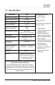
GP-PWM-30 ________________________________________________________________________ 1.2 Specifications Description Value Nominal System Voltage 12V Max. Solar Array Current 30 amps Battery Voltage Range Max. Solar Voltage Dimensions (H x W x D): 107 x 190 x 35 mm 4.25 x 7.5 x 1.38 in Weight: 172 grams 6 oz Maximum Wire Gauge: #6 AWG Warranty: 5 years 6V – 15.5V 28V Operating Consumption Display Consumption 6mA 10mA Bulk/Absorption Voltage 14.1/14.
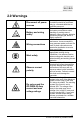
GP-PWM-30 ________________________________________________________________________ 2.0 Warnings Disconnect all power sources Battery and wiring safety Wiring connections Work safely Observe correct polarity Do not exceed the GP-PWM-30 Amp current and max voltage ratings Electricity can be very dangerous. Installation should be performed only by a licensed electrician or qualified personnel. Observe all safety precautions of the battery manufacturer when handling or working around batteries.
GP-PWM-30 ________________________________________________________________________ 3.0 Tools and Materials Needed • Phillips Screwdriver If the GP-PWM-30 Controller was purchased with a Go Power! RV Solar Power Kit then UV resistant wire is included. For instructions regarding the Go Power! RV Solar Power Kit installation, please refer to the Installation Guide provided with the Kit. 4.0 Choosing a Location The GP-PWM-30 is designed to be mounted flush against a wall, out of the way but easily visible.
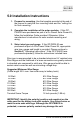
GP-PWM-30 ________________________________________________________________________ 5.0 Installation Instructions 1. Prepare for mounting. Use the template provided at the end of the manual to mark the four mounting holes and the “cutting line for flush mounting.” 2. Complete the installation of the solar modules. If this GPPWM-30 was purchased as part of a Go Power! Solar Power Kit, follow the Installation Guide provided. Otherwise, follow manufacturer’s instructions for solar module mounting and wiring.
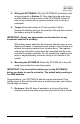
GP-PWM-30 ________________________________________________________________________ 4. Wiring the GP-PWM-30. Wire the GP-PWM-30 according to the wiring schematic in Section 11. Run wires from the solar array and the batteries to the location of the GP-PWM-30. Keep the solar array covered with an opaque material until all wiring is completed. 5. Torque all terminal screws to 16 inch pounds (1.8N.m). Connect the battery wiring to the controller first and then connect the battery wiring to the battery.
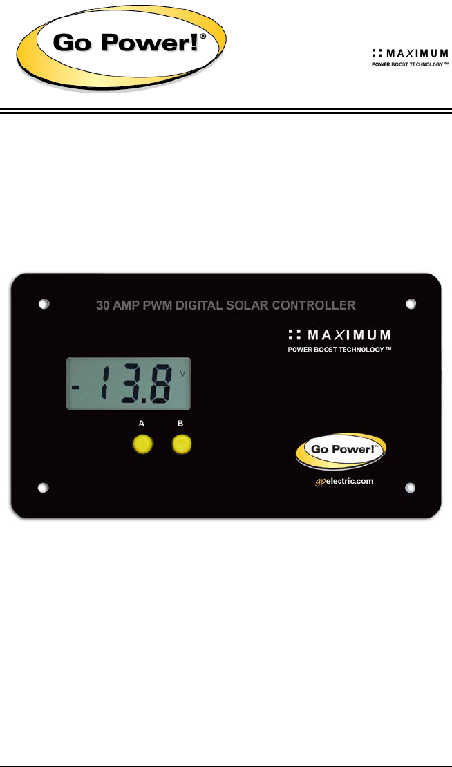
GP-PWM-30 ________________________________________________________________________ 6.0 Operating Instructions Power Up When the GP-PWM-30 is connected to the battery, the GP-PWM-30 will go into Power Up mode. Icons Displayed: Three horizontal dashes Setting the Battery Type / Charging Profile Set the Battery Type / Charging Profile by holding down the B Button for 5 seconds. When the display shows a single digit number, release the B Button.
GP-PWM-30 ________________________________________________________________________ Refer to the Battery Charge Profile Chart on page 13 for details on each profile. Confirm the Battery Type / Charging Profile selection by pressing the A Button. Depending on the battery voltage when the GP-PWM-30 Power Up occurs, the GP-PWM-30 may do a Boost Charge or quickly go into Float Charge. The Charging Profile selected will commence the following day after a Power Up.
GP-PWM-30 ________________________________________________________________________ Maximum Power Boost Technology™ Maximum Power Boost Technology™ (MPBT) is a new feature on the GP-PWM-30 that allows you to override the normal charging algorithm of the solar controller. This feature will make the GP-PWM-30 go into a boost mode, bringing the voltage up to 14.4 VOC for 30 minutes regardless of the batteries state of charge.
GP-PWM-30 ________________________________________________________________________ Battery Charge Profile Chart Battery Type Charging Profile # FLOODED AGM GEL 1 2 3 Float Charge @ 25°C: Bulk/Absorption Charge @ 25°C: Applied for 1h each morning 13.7V (+/- 0.1V) 14.4V (+/- 0.1V) 14.1V (+/- 0.1V) 14.4V (+/- 0.7V) 14.1V (+/- 0.1V) Boost Charge Applied for 2 hours if the battery voltage drops below 12.3 volts.
GP-PWM-30 ________________________________________________________________________ Viewing the Controller display information To toggle between State of Charge (SOC), Battery Voltage and PV Charging Current, press the B Button. The battery state of charge is shown as a percentage. Icons Displayed: Battery, Percent Symbol Push the B Button to show the battery voltage. Icons Displayed: Battery, Volt Symbol (V) Push the B Button to show the PV charging current.
GP-PWM-30 ________________________________________________________________________ Errors Over Voltage If the GP-PWM-30 experiences a battery over voltage (15.5V), the controller will stop operating and the display will begin to flash. The controller will resume operating when the error is cleared.
GP-PWM-30 ________________________________________________________________________ 7.0 Frequently Asked Questions (FAQs) Before a problem is suspected with the system, read this section. There are numerous events that may appear as problems but are in fact perfectly normal. Please visit gpelectric.com for the most up-to-date FAQs. It seems like my flooded batteries are losing water over time. Flooded batteries may need to have distilled water added periodically to replace fluid loss during charging.
GP-PWM-30 ________________________________________________________________________ 8.0 Troubleshooting Problems How to read this section Troubleshooting Problems is split into three sub-sections, grouped by symptoms involving key components. Components considered irrelevant in a diagnosis are denoted ‘Not Applicable’ (N/A). A multimeter or voltmeter may be required for some procedures listed.
GP-PWM-30 ________________________________________________________________________ 8.2 Problems with Voltage Voltage Reading: Inaccurate Time of Day: Daytime/Nighttime Possible Cause: (1) Excessive voltage drop from batteries to controller due to loose connections, small wire gauge or both. How to tell: (1) Check the voltage at the controller battery terminals with a voltmeter and compare with the voltage reading at the battery terminals. If there is a voltage discrepancy of more than 0.
GP-PWM-30 ________________________________________________________________________ Current Reading: Less than expected Time of Day: Daytime, clear sunny skies Possible Cause: (1) Current is being limited below 1 Amp as per normal operation. (2) Incorrect series/parallel configuration and/or wiring connections and/or wire gauge. (3) Dirty or shaded module or lack of sun. (4) Blown diode in solar module when two or more modules are connected in parallel.
GP-PWM-30 ________________________________________________________________________ 9.0 Limited Warranty 1. Carmanah warrants the GP-PWM-30 for a period of five (5) years from the date of shipment from its factory. This warranty is valid against defects in materials and workmanship for the five (5) year warranty period.
GP-PWM-30 ________________________________________________________________________ 11.0 Wiring Diagram Solar Array The GP-PWM-30 is based on a 30 amp max input from the solar modules. E.G. Three modules in parallel with an input of 7 amps each equal a total input of 21 amps. Most solar modules list the input amps on their specifications label.
GP-PWM-30 ________________________________________________________________________ 22 © 2018 Go Power! By Valterra Power
GP-PWM-30 ________________________________________________________________________ 23 © 2013 Carmanah Technologies Corporation
© 2018 Go Power! By Valterra Power MOBI_MAN_GP-PWM-30_vE gpelectric.