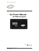
Owner’s Manual | GP-PWM-25 Regulator Go Power! Manual GP-PWM-25 Regulator 1 © 2010 Carmanah Technologies Corporation Last revised March 2010
Owner’s Manual | GP-PWM-25 Regulator 2 © 2010 Carmanah Technologies Corporation Last revised March 2010
Owner’s Manual | GP-PWM-25 Regulator CONTENTS 1.0 Installation Overview 1.1 Introduction 1.2 Specifications 5 5 6 2.0 Warnings 7 3.0 Tools and Materials Needed 8 4.0 Choosing a Location 8 5.0 Installation Instructions 9 6.0 Operating Instructions 11 7.0 Before You Read Troubleshooting 14 8.0 Troubleshooting Problems 8.1 Problems with the Display 8.2 Problems with Voltage 8.3 Problems with Current 15 15 15 16 9.0 Limited Warranty 9.1 General Warranty Issues 9.
Owner’s Manual | GP-PWM-25 Regulator 4 © 2010 Carmanah Technologies Corporation Last revised March 2010
Owner’s Manual | GP-PWM-25 Regulator 1.0 Installation Overview 1.1 Introduction A Charge Regulator is an essential component of your photovoltaic (PV) system. The Regulator maintains the life of the battery by protecting it from overcharging. When your battery has reached a 100% state of charge, the Regulator prevents overcharging by limiting the current flowing into the batteries from your solar array.
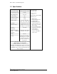
Owner’s Manual | GP-PWM-25 Regulator 1.2 Specifications Description Value Nominal System Voltage 12/24V, automatic selection Max. Solar Array Current 25 Amps Battery Voltage Range 6V – 31V Max. Solar Voltage 56V Operating Consumption 6mA Display Consumption 10mA Absorption Voltage 14.1/14.4V 28.2/28.8V (25°C / 77°F), 0.5-2h / Day Float Voltage 13.7/27.4V (25°C / 77°F) Equalization Voltage 14.8/29.6V (25°C / 77°F), 2h / 28 Day or V < 12.1/24.
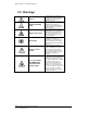
Owner’s Manual | GP-PWM-25 Regulator 2.0 Warnings Disconnect all power sources Battery and wiring safety Wiring connections Work safely Observe correct polarity Do not exceed the GP-PWM-25 Amp current and max voltage ratings 7 © 2010 Carmanah Technologies Corporation Last revised March 2010 Electricity can be very dangerous. Installation should be performed only by a licensed electrician or qualified personnel.
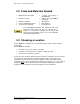
Owner’s Manual | GP-PWM-25 Regulator 3.0 Tools and Materials Needed Drill with 3/32” and 3/8 bits Keyhole or Jigsaw Phillips Screwdriver Pencil or Marking Implement Torque wrench (optional) UV Wire (Solar Array) to GP-PWM-25)* Battery Wire (GP-PWM-25 to Battery)* Wire Cutters Wire Strippers Electrical Tape If the GP-PWM-25 Regulator was purchased with a Go Power! RV Solar Power Kit then UV resistant wire is included.
Owner’s Manual | GP-PWM-25 Regulator 5.0 Installation Instructions 1. Prepare for mounting. Use the template provided at the end of the manual to mark the four mounting holes and the “cutting line for flush mounting.” 2. Complete the installation of the solar modules. If this GP-PWM-25 was purchased as part of a Go Power! Solar Power Kit, follow the Installation Guide provided. Otherwise follow manufacturer’s instructions for solar module mounting and wiring. 3. Select wire type and gauge.
Owner’s Manual | GP-PWM-25 Regulator 4. Wiring the GP-PWM-25. Wire the GP-PWM-25 according to the wiring schematic in Section 11. Run wires from the solar array and the batteries to the location of the GP-PWM-25. Keep the solar array covered with an opaque material until all wiring is completed. Torque all terminal screws to 16 inch pounds (1.8N.m) Connect the battery wiring to the regulator first and then connect the battery wiring to the battery.
Owner’s Manual | GP-PWM-25 Regulator 6.0 Operating Instructions Power Up When the GP-PWM-25 is connected to the battery, the GP-PWM-25 will go into Power Up mode. The controller will select the battery voltage automatically. If the battery voltage is above 20 Volts the controller assumes a 24 Volt battery system. Icons Displayed: Three horizontal dashes Setting the Battery Type / Charging Profile Set the Battery Type / Charging Profile by holding down the B Button for 10 seconds.
Owner’s Manual | GP-PWM-25 Regulator Confirm the Battery Type / Charging Profile selection by pressing the A Button. Depending on the battery voltage when the GP-PWM-25 Power Up occurs, the GP-PWM-25 may do a Boost Charge or quickly go into Float Charge. The Charging Profile selected will commence the following day after a Power Up. Battery Charge Profile Chart Battery Type Charging Profile # FLOODED AGM GEL 1 2 3 Float Charge @ 25°C: 13.7 / 27.4V Bulk/Absorption Charge @ 25°C: 14.1 / 28.
Owner’s Manual | GP-PWM-25 Regulator Viewing the Regulator display information To toggle between State of Charge (SOC), Battery Voltage and PV Charging Current, press the B Button. The battery state of charge is shown as a percentage. Icons Displayed: Battery, Percent Symbol Push the B Button to show the battery voltage. Icons Displayed: Battery, Volt Symbol (V) Push the B Button to show the PV charging current. The GP-PWM-25 will begin to limit the current as the battery reaches a full charge.
Owner’s Manual | GP-PWM-25 Regulator 7.0 Before You Read Troubleshooting Before a problem is suspected with the system, read this section. There are numerous events that may appear as problems but are in fact perfectly normal. It seems like my flooded batteries are losing water over time. Flooded batteries may need to have distilled water added periodically to replace fluid loss during charging. Excessive water loss during a short period of time indicates the possibility of overcharging or aging batteries.
Owner’s Manual | GP-PWM-25 Regulator 8.0 Troubleshooting Problems How to read this section Troubleshooting Problems is split into three sub-sections, grouped by symptoms involving key components. Components considered irrelevant in a diagnosis are denoted ‘Not Applicable’ (N/A). A multimeter or voltmeter may be required for some procedures listed. It is imperative all electrical precautions stated in the Warning Section and outlined in the Installation Section are followed.
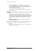
Owner’s Manual | GP-PWM-25 Regulator 8.3 Problems with Current Current Reading: 0 A Time of Day: Daytime, clear sunny skies Possible Cause: (1) Current is being limited below 1 Amp as per normal operation. (2) Poor connection between solar array and regulator How to tell: (1) The State of Charge (SOC) screen is close to 100% and the Sun and Battery icon are present with an arrow between. (2) With the solar array in sunlight, check the voltage at the regulator solar array terminals with a voltmeter.
Owner’s Manual | GP-PWM-25 Regulator 9.0 Limited Warranty 1. Carmanah warrants the GP-PWM-25 for a period of five (5) years from the date of shipment from its factory. This warranty is valid against defects in materials and workmanship for the five (5) year warranty period. It is not valid against defects resulting from, but not limited to: Misuse and/or abuse, neglect or accident.
Owner’s Manual | GP-PWM-25 Regulator 9.1 General Warranty Issues Please refer to the manufacturers’ warranty sheet(s). 1. Carmanah cannot assume responsibility for any damages to any system components used in conjunction with Carmanah products nor for claims for personal injury or property damage resulting from the use of Carmanah products or the improper operation thereof or consequential damages arising from the products or use of the products. 2.
Owner’s Manual | GP-PWM-25 Regulator 9.2 Repair and Return Information To return items: 1. Call your Carmanah dealer or Carmanah’s technical SUPPORT (1-800-6676527) to try and troubleshoot the problem. 2. Obtain an RMA # by calling your Carmanah sales representative or the RMA department customerservice@carmanah.com. 3. Ensure the RMA # is clearly visible on the outside of the package, or THE PACKAGE WILL BE REFUSED. 4.
Owner’s Manual | GP-PWM-25 Regulator 10.0 Glossary Ampere: A unit of electrical current. Designates the number of electrons flowing per second through a conductive material. Array: One or more photovoltaic (PV) modules electrically connected to produce a single electrical output. Battery: Two or more electrochemical cells connected to provide energy storage. May be used to designate one cell. PV system batteries may be “sealed” or “wet acid”.
Owner’s Manual | GP-PWM-25 Regulator 11.
Owner’s Manual | GP-PWM-25 Regulator 12.0 Wiring Diagram SOLAR ARRAY THE GP-PWM-25 IS BASED ON A 25 AMP MAX FOR THE TOTAL IMP OF THE SYSTEM. E.G. THREE MODULES IN PARALLEL WITH AN IMP OF 7 AMPS EACH EQUALS A TOTAL IMP OF 21 AMPS. MOST SOLAR MODULES LIST THE IMP ON THEIR SPECIFICATIONS LABEL. FUSE BATTERY BANK SUGGESTED FUSE SIZE #14 WIRE = 15 AMP FUSE #12 WIRE = 20 AMP FUSE #10 WIRE = 30 AMP FUSE NOTE: THE FUSE IS INTENDED TO PROTECT THE WIRE.
Owner’s Manual | GP-PWM-25 Regulator 23 © 2010 Carmanah Technologies Corporation Last revised: March 2010
© 2010 Carmanah Technologies Corporation carmanah.com Technical Support: info@gpelectric.com Toll Free (US and Canada): 1-800-667-6527 Worldwide: 1-250-652-5233 Toll Free Fax (US and Canada): 1-866-607-6527 Number: 57175_MAN_GP-PWM-25 Regulator_RevE 8.