
User Manual

GP-SW1000/2000/3000
___________________________________________________________
23
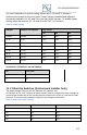
For more information on power saving, please see 5.10 and 5.11 sections
Switches are located on the front panel. Power saving is enabled and adjusted
through dip switches S1, S2, and S3 on the front of the inverter. To disable power
saving, leave dip switches S1, S2 and S3 in the OFF or 0 position
Table 3: Power Saving
SW1000
SW2000 and SW3000
Dip Switch
S1
S2
S3
Disable
Disable
OFF
OFF
OFF
20 W
40 W
ON
OFF
OFF
40 W
80 W
OFF
ON
OFF
55 W
125 W
ON
ON
OFF
75 W
170 W
OFF
OFF
ON
95 W
210 W
ON
OFF
ON
115 W
245 W
OFF
ON
ON
135 W
280 W
ON
ON
ON
GP-SW1000, GP-SW2000, and GP-SW3000
S4
Freq. (Hz)
0
50
1
60
10. 2 Other Dip Switches (Professional Installer Only)
The default voltage setting for the GP-SW1000, GP-SW2000, and
GP-SW3000 is 115 V AC, however all these inverters may be configured for other voltages by
a professional installer via the two red dip switches located close to the AC connection inside
each unit. The unit must be restarted in order for any changes to take effect.
Table 4: Other Dip Switch Settings
SW1
SW2
VAC
Off
Off
100
On
Off
110
Off
On
115
On
On
120